Popular Woodworking 2006-02 № 153, страница 33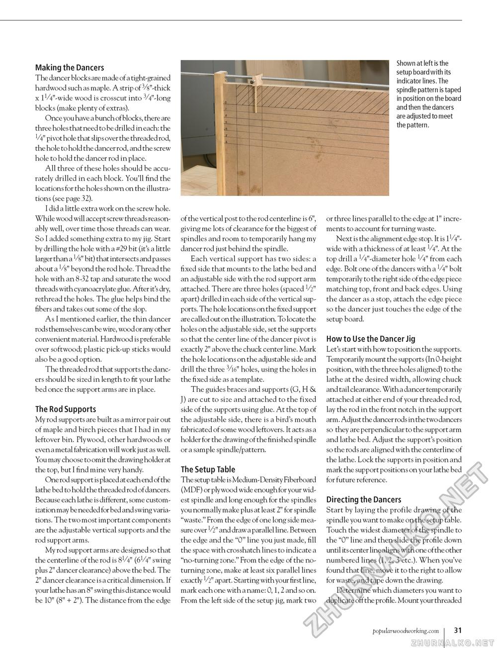
Making the Dancers The dancer blocks are made of a tight-grained hardwood such as maple. A strip of 3/8"-thick x lVV'-wide wood is crosscut into 3/4"-long blocks (make plenty of extras). Once you have a bunch of blocks, there are three holes that need to be drilled in each: the V4" pivot hole that slips over the threaded rod, the hole to hold the dancer rod, and the screw hole to hold the dancer rod in place. All three of these holes should be accurately drilled in each block. You'll find the locations for the holes shown on the illustrations (see page 32). I did a little extra work on the screw hole. While wood will accept screw threads reasonably well, over time those threads can wear. So I added something extra to my jig. Start by drilling the hole with a #29 bit (it's a little larger than a V8" bit) that intersects and passes about a V8" beyond the rod hole. Thread the hole with an 8-32 tap and saturate the wood threads with cyanoacrylate glue. After it's dry, rethread the holes. The glue helps bind the fibers and takes out some of the slop. As I mentioned earlier, the thin dancer rods themselves can be wire, wood or any other convenient material. Hardwood is preferable over softwood; plastic pick-up sticks would also be a good option. The threaded rod that supports the dancers should be sized in length to fit your lathe bed once the support arms are in place. The Rod Supports My rod supports are built as a mirror pair out of maple and birch pieces that I had in my leftover bin. Plywood, other hardwoods or even a metal fabrication will work just as well. You may choose to omit the drawing holder at the top, but I find mine very handy. One rod support is placed at each end of the lathe bed to hold the threaded rod of dancers. Because each lathe is different, some customization may be needed for bed and swing variations. The two most important components are the adjustable vertical supports and the rod support arms. My rod support arms are designed so that the centerline of the rod is 8V4" (6V4" swing plus 2" dancer clearance) above the bed. The 2" dancer clearance is a critical dimension. If your lathe has an 8" swing this distance would be 10" (8" + 2"). The distance from the edge of the vertical post to the rod centerline is 6", giving me lots of clearance for the biggest of spindles and room to temporarily hang my dancer rod just behind the spindle. Each vertical support has two sides: a fixed side that mounts to the lathe bed and an adjustable side with the rod support arm attached. There are three holes (spaced V2" apart) drilled in each side of the vertical supports. The hole locations on the fixed support are called out on the illustration. To locate the holes on the adjustable side, set the supports so that the center line of the dancer pivot is exactly 2" above the chuck center line. Mark the hole locations on the adjustable side and drill the three 3/l6" holes, using the holes in the fixed side as a template. The guides braces and supports (G, H & J) are cut to size and attached to the fixed side of the supports using glue. At the top of the adjustable side, there is a bird's mouth fabricated of some wood leftovers. It acts as a holder for the drawing of the finished spindle or a sample spindle/pattern. The Setup Table The setup table is Medium-Density Fiberboard (MDF) or plywood wide enough for your widest spindle and long enough for the spindles you normally make plus at least 2" for spindle "waste." From the edge of one long side measure over V2" and draw a parallel line. Between the edge and the "0" line you just made, fill the space with crosshatch lines to indicate a "no-turning zone." From the edge of the no-turning zone, make at least six parallel lines exactly V2" apart. Starting with your first line, mark each one with a name: 0, 1, 2 and so on. From the left side of the setup jig, mark two Shown at left is the setup board with its indicator lines. The spindle pattern is taped in position on the board and then the dancers are adjusted to meet the pattern. or three lines parallel to the edge at 1" increments to account for turning waste. Next is the alignment edge stop. It is 11/4"-wide with a thickness of at least V4". At the top drill a VV-diameter hole V4" from each edge. Bolt one of the dancers with a V4" bolt temporarily to the right side of the edge piece matching top, front and back edges. Using the dancer as a stop, attach the edge piece so the dancer just touches the edge of the setup board. How to Use the Dancer Jig Let's start with how to position the supports. Temporarily mount the supports (In 0-height position, with the three holes aligned) to the lathe at the desired width, allowing chuck and tail clearance. With a dancer temporarily attached at either end of your threaded rod, lay the rod in the front notch in the support arm. Adjust the dancer rods in the two dancers so they are perpendicular to the support arm and lathe bed. Adjust the support's position so the rods are aligned with the centerline of the lathe. Lock the supports in position and mark the support positions on your lathe bed for future reference. Directing the Dancers Start by laying the profile drawing of the spindle you want to make on the setup table. Touch the widest diameter of the spindle to the "0" line and then slide the profile down until its center line aligns with one of the other numbered lines (1, 2, 3 etc.). When you've found that line, move it to the right to allow for waste, and tape down the drawing. Determine which diameters you want to duplicate off the profile. Mount your threaded popularwoodworking.com I 103 |


