41 - Fold-Down Drafting Table, страница 9
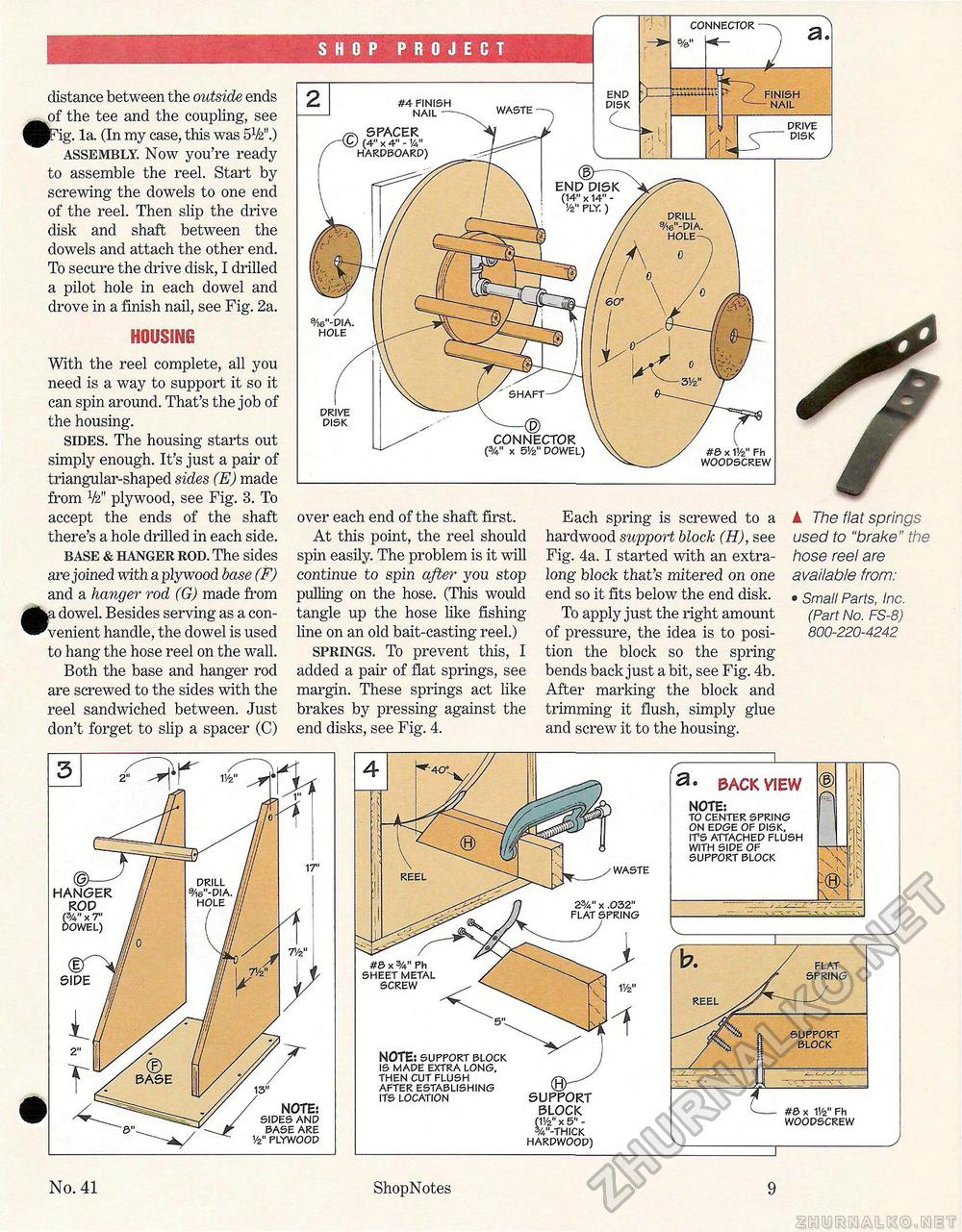
distance between the outside ends of the tee and the coupling, see JPig. la. (In my case, this was 5V2".) assembly. Now you're ready to assemble the reel. Start by screwing the dowels to one end of the reel. Then slip the drive disk and shaft between the dowels and attach the other end. To secure the drive disk, I drilled a pilot hole in each dowel and drove in a finish nail, see Fig. 2a. HOUSING With the reel complete, all you need is a way to support it so it can spin around. That's the job of the housing. sides. The housing starts out simply enough. It's just a pair of triangular-shaped sides (E) made from V2" plywood, see Fig. 3. To accept the ends of the shaft there's a hole drilled in each side. base & hanger rod. The sides are joined with a plywood base (F) and a hanger rod (G) made from r, dowel. Besides serving as a convenient handle, the dowel is used to hang the hose reel on the wall. Both the base and hanger rod are screwed to the sides with the reel sandwiched between. Just don't forget to slip a spacer (C) over each end of the shaft first. At this point, the reel should spin easily. The problem is it will continue to spin after you stop pulling on the hose. (This would tangle up the hose like fishing line on an old bait-casting reel.) springs. To prevent this, I added a pair of flat springs, see margin. These springs act like brakes by pressing against the end disks, see Fig. 4. Each spring is screwed to a hardwood support block (H), see Fig. 4a. I started with an extra-long block that's mitered on one end so it fits below the end disk. To apply just the right amount of pressure, the idea is to position the block so the spring bends back just a bit, see Fig. 4b. After marking the block and trimming it flush, simply glue and screw it to the housing. ▲ The flat springs used to "brake" the hose reel are available from: • Small Parts, Inc. (Part No. FS-8) 800-220-4242 WASTE , SPACER ) (4" x 4" - 14" HARDBOARD) END DISK (14" x 14" -1/2" PLY. ) DRILL 9/i6"-DIA. HOLE- SHAFT CONNECTOR (%" x 5!/2" DOWEL) SHOP PROJECT DISK. DRIVE DISK #4 FINISH NAIL — CONNECTOR CS 0 FINISH NAIL #& x 11/2" Fh WOODSCREW 9/i6"-DIA. HOLE DRIVE DISK #3 x 5A" Ph SHEET METAL SCREW NOTE: support block IS MADE EXTRA LONG, THEN CUT FLUSH AFTER ESTABLISHING ITS LOCATION SUPPORT BLOCK ril/2" x 5" - %"-THICK HARDWOOD) WASTE REEL SUPPORT BLOCK a- BACK VIEW NOTE: TO CENTER SPRING ON EDGE OF DISK, ITS ATTACHED FLUSH WITH SIDE OF SUPPORT BLOCK REEL #8 x V/z" Fh WOODSCREW FLAT SPRING No. 41 ShopNotes 9 |


