Woodworker's Journal 1985-9-3, страница 48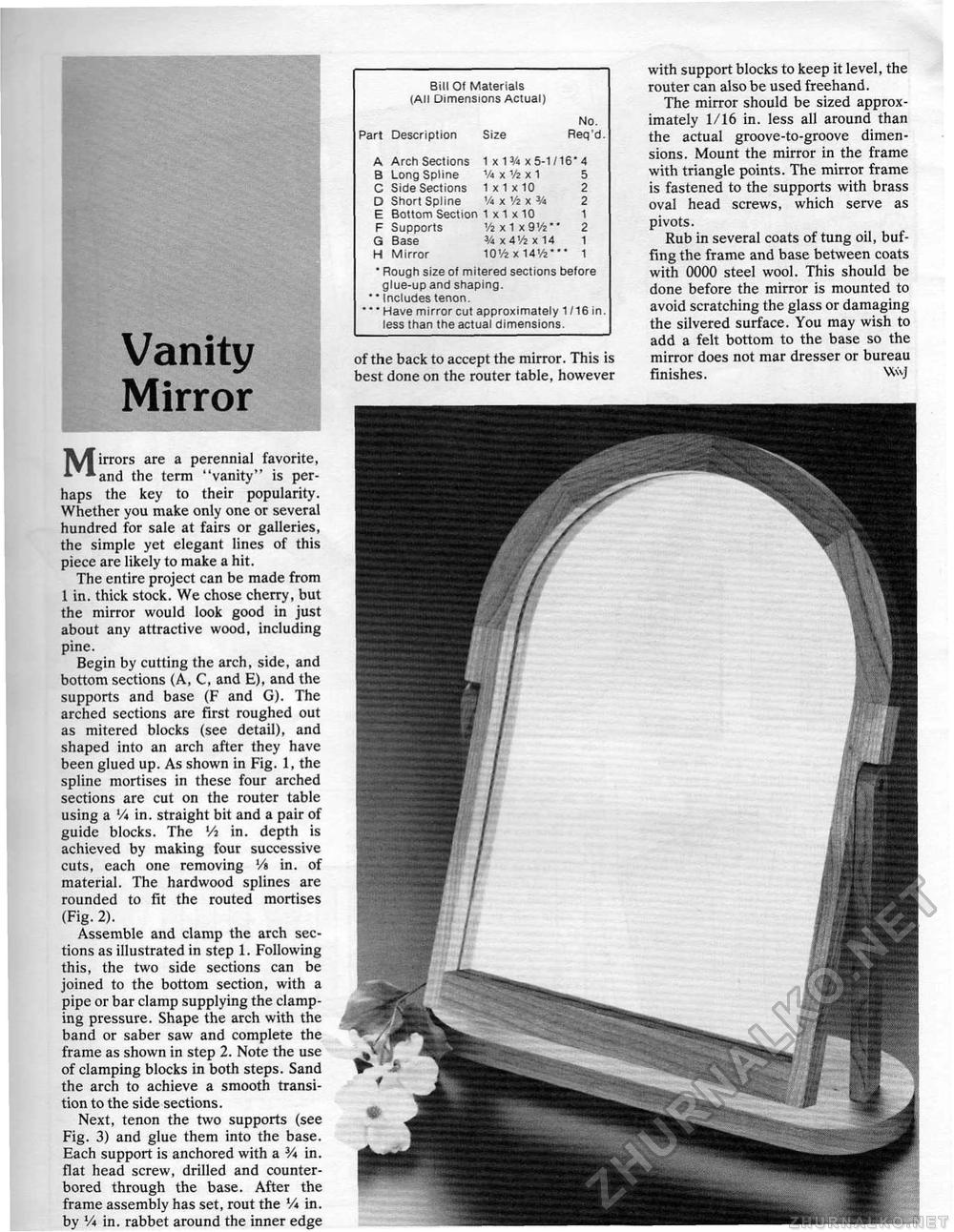
Vanity Mirror Bill Of Materials (All Dimensions Actual) Part Description Size No. Req'd. Part Description Size
* Rough size of mitered sections before glue-up and shaping. ' * Includes tenon. * * Have mirror cut approximately 1/16 in. less than the actual dimensions. * Rough size of mitered sections before glue-up and shaping. ' * Includes tenon. * * Have mirror cut approximately 1/16 in. less than the actual dimensions. of the back to accept the mirror. This is best done on the router table, however with support blocks to keep it level, the router can also be used freehand. The mirror should be sized approximately 1/16 in. less all around than the actual groove-to-groove dimensions. Mount the mirror in the frame with triangle points. The mirror frame is fastened to the supports with brass oval head screws, which serve as pivots. Rub in several coats of tung oil, buffing the frame and base between coats with 0000 steel wool. This should be done before the mirror is mounted to avoid scratching the glass or damaging the silvered surface. You may wish to add a felt bottom to the base so the mirror does not mar dresser or bureau finishes. WvJ ^^irrors are a perennial favorite, * *and the term "vanity" is perhaps the key to their popularity. Whether you make only one or several hundred for sale at fairs or galleries, the simple yet elegant lines of this piece are likely to make a hit. The entire project can be made from 1 in. thick stock. We chose cherry, but the mirror would look good in just about any attractive wood, including pine. Begin by cutting the arch, side, and bottom sections (A, C, and E), and the supports and base (F and G). The arched sections are first roughed out as mitered blocks (see detail), and shaped into an arch after they have been glued up. As shown in Fig. 1, the spline mortises in these four arched sections are cut on the router table using a '/« in. straight bit and a pair of guide blocks. The lA in. depth is achieved by making four successive cuts, each one removing V% in. of material. The hardwood splines are rounded to fit the routed mortises (Fig. 2). Assemble and clamp the arch sections as illustrated in step 1. Following this, the two side sections can be joined to the bottom section, with a pipe or bar clamp supplying the clamping pressure. Shape the arch with the band or saber saw and complete the frame as shown in step 2. Note the use of clamping blocks in both steps. Sand the arch to achieve a smooth transition to the side sections. Next, tenon the two supports (see Fig. 3) and glue them into the base. Each support is anchored with a 3A in. flat head screw, drilled and counter-bored through the base. After the frame assembly has set, rout the Vi in. by Vi in. rabbet around the inner edge |
||||||||||||||||||||||||||||||||


