Woodworker's Journal 1992-16-6, страница 38
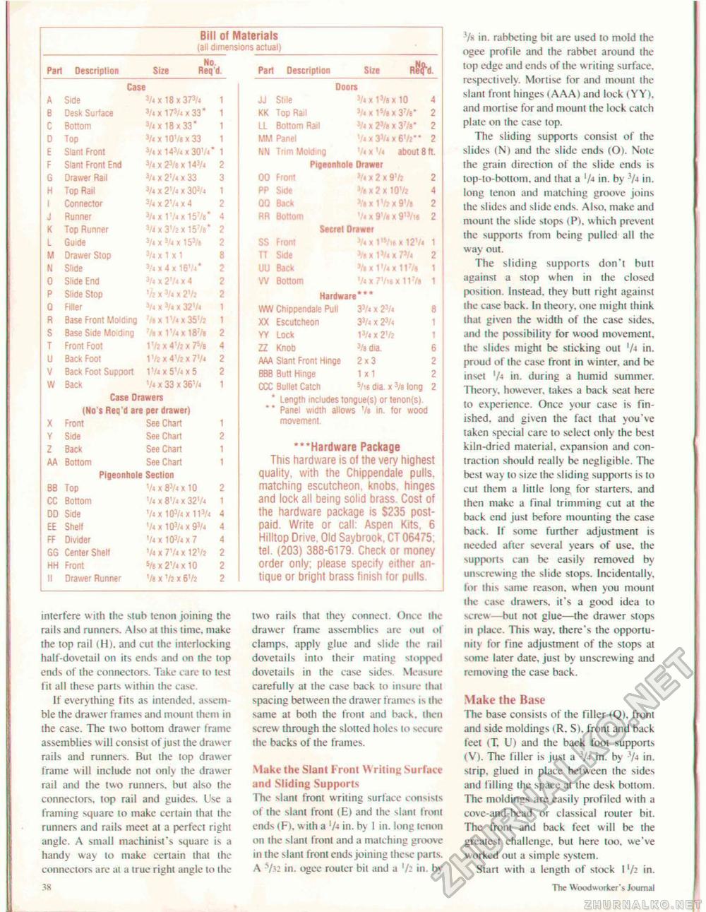
interfere with the stub tenon joining the rails and runners. Also ai this time, make the top rail (H). and cut the interlocking half-dovetail on its ends and on the top ends of the connectors. Take care to test fit all these parts within the ease. If everything fits as intended, assemble the drawer frames and mount them in the case. The two bottom drawer frame assemblies will consist of just the drawer rails and runners. But the top drawer frame will include not only the drawer rail and the two runners, but also the connectors, top rail and guides. Use a framing square lo make certain that the runners and rails meet at a perfect right angle. A small machinist's square is a handy way lo make certain that the connectors are at a true right tingle lo the •4K two rails that they connect. Once ihe drawer frame assemblies are out of clamps, apply glue and slide the rail dovetails into their mating stopped dovetails in the case sides. Measure carefully al the case back to insure that spacing between the drawer frames is the same at both the front and back, then screw through the slotted holes to secure the backs of the frames. Make the Slant Front Writing Surface and Sliding Supports The slant front writing surface consists of the slant front (E) and ihe slant Irom ends (F), wiih a 'A in. by 1 in. long tenon on the slant front and a matching groove in the slant from ends joining these parts. A -s/.i- in. ogee router bit and a '/; in. by -7s in. rabbeting bit are used to mold the ogee profile and the rabbet around the lop edge and ends of the w riling surface, respectively. Moriise for and mount the slant front hinges (.AAA) and lock (YY). and mortise for and mount the lock catch plate on the case top. llie sliding supports consist of the slides (N) and the slide ends (O). Note ihe grain direction of (he slide ends is top-to-bottom, and that a 'A in. by V-t in. long tenon and matching groove joins the slides and slide ends. Also, make and mount the slide stops (P), which prevent the supports from being pulled ail (he way out. The sliding supports don'l butt against a stop when in the closed posilion. Instead, they butt righl against the case back. In theory, one might think that given the w idth of Ihe case sides, and the possibility for wood movement, ihe slides might be slicking out 'A in. proud of the case front in winter, and be inset 'A in. during a humid summer. Theory, however, takes a back seal hereto experience. Once your case is finished. and given the fact lhat you've taken special care to select only the besi kiln-dried material, expansion and contraction should really be negligible. The best way lo size ihe sliding supports is lo cut them a liltle long for starters, and then make a final trimming cut at the back end just before mounting the case back. If some further adjustment is needed alter several years of use, the supports can be easily removed by unscrewing ihe slide stops. Incidentally, tor this same reason, when you mount the case drawers, it's a good idea to screw—hut not glue—the drawer stops til place. This way. there's ihe opportunity for fine adjustmenl of the stops at some later date, just by unscrewing and removing the case back. Make the Base The base consists of the filler (Q), front and side moldings < R. S). front and back feet (T, U) and the back foot supports (V). The filler is just a 3A in. by 'A in. sirip. glued in place between the sides and filling the space al the desk bottom. The moldings are easily profiled w ith a cove-and-bead or classical router bit. The front and back feel will be the greatest challenge, but here too, we've worked out a simple system. Start with a length of stock I xh in. The Woodworker's Journal |
||||||||||||||||||||||||||||||||||||||||||||||||||||||||||||||||||||||||||||||||||||||||||||||||||||||||||||||||||||||||||||||||||||||||||||||||||||||||||||||||||||||||||||||||||||||||||||||||||||||||||||||||||


