Woodworker's Journal 1994-18-6, страница 28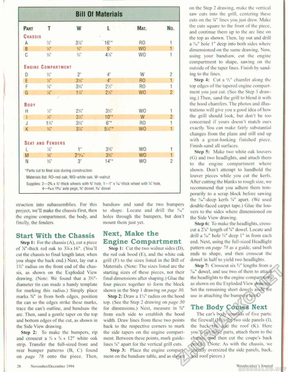
struction into subassemblies. For this project, we'll make the chassis first, then the engine compartment, the body, and finally, the fenders. Start With the Chassis Step ): For the chassis (A), cut a piece of /."-thick red oak to 37/«xl6". (You'll cut the chassis to final length later, when you shape the back end.) Next, lay out a 1 y*" radius on the front end of the chassis, as shown on the Exploded View drawing. (Note: We found that a 3/:"-diameter tin can made a handy template for marking this radius.) Simply place marks %" in from both edges, position the can so the edges strike these marks, trace the can's outline, and bandsaw the arc. Then, sand a gentle taper on the top and bottom edges of the cut, as shown in the Side View drawing. Step 2: To make the bumpers, rip and crosscut a 'A x V* * 12" white oak strip. Transfer the full-sized front and rear bumper patterns (B, C) found on page 78 onto the piece. Then, bandsaw and sand the two bumpers to shape. Locate and drill the Vu" holes through the bumpers, but don't mount them just yet. Next, Make the Engine Compartment Step 1: Cut the two walnut sides (D), the red oak hood (E), and the white oak grill (F) to the sizes listed in the Bill of Materials. (Note: The sizes listed arc the starting sizes of these pieces, not their final dimensions after shaping.) Glue the four pieces together to form the block shown in the Step 1 draw ing on page 30. Step 2: Draw a VA" radius on the hood top. (See the Step 2 drawing on page 30 for dimensions.) Next, measure in V*" from each side to establish the hood width. Draw lines from these two points back to the respective corners to mark the side tapers on the engine compartment. Between these points, mark guidelines '/«" apart for the vertical grill cuts. Step 3: Place the engine compartment on the bandsaw table, and as shown on the Step 2 draw ing, make the vertical saw cuts into the grill, centering these cuts on the V*" lines you just drew. Make the cuts square to the front of the piece, and continue them up to the arc line on the top as shown. Then, lay out and drill a V hole !" deep into both sides where dimensioned on the same drawing. Now. using your bandsaw, cut the engine compartment to shape, sawing on the outside of the taper lines. Finish by sanding to the lines. Step 4: Cut a '/:" chamfer along the top edges of the tapered engine compartment you just cut. (See the Step 3 drawing.) Then, sand the grill to blend it with the hood chamfers. The photos and illustrations will give you a good idea of how the grill should look, but don't be too concerned if yours doesn't match ours exactly. You can make fairly substantial changes from the plans and still end up with a great-looking finished piece. Finish-sand all surfaces. Step 5: Make two white oak louvers (G) and two headlights, and attach them to the engine compartment where shown. Don't attempt to handhold the louver pieces while you cut the kerfs. After cutting the blanks to rough size, we recommend that you adhere them temporarily to a scrap block before sawing the V-dcep kerfs '/«" apart. (We used double-faced carpet tape.) Glue the louvers to the sides where dimensioned on the Side View draw ing. Step 6: To make the headlights, crosscut a 2%" length of %" dowel. Locate and drill a V hole V" deep 1" in from each end. Next, using the full-sized Headlight pattern on page 78 as a guide, sand botfi ends to shape, and then crosscut the dowel in half to yield two headlights. Step 7: Crosscut six V" lengths from a »/,." dow el, and use two of them to attach the headlights to the engine compartment as shown on the Exploded View drawing. Set the remaining short dowels aside for use in attaching the bumpers later. The Body Comes Next The car's body consists of five parts: the firewall (H), the two side panels (I), the back (J), and the roof (K). Here you'll cut these parts, attach them to the chassis, and then cut the coupe's back profile. (Note: As with the chassis, we initially oversized the side panels, back, and roof pieces.) 28 Novemher/December 1994 Wixxiworkcr's Journal |
||||||||||||||||||||||||||||||||||||||||||||||||||||||||||||||||||||||||||||||||||||||||||||||||||||||||||||||||||||||||


