40 - Vacuum Clamping System, страница 29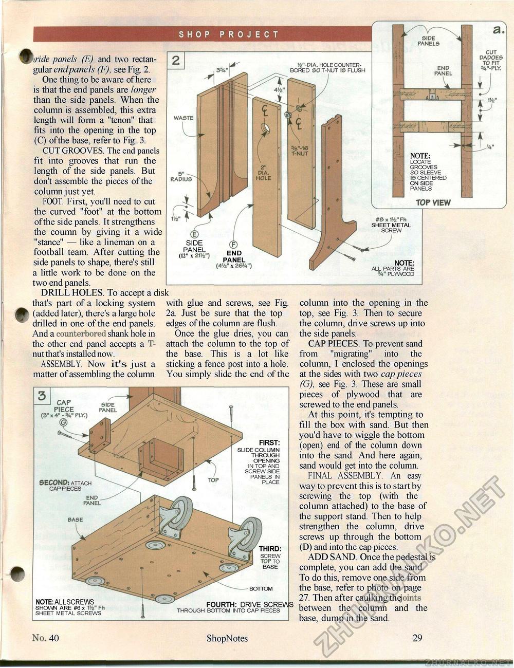
SHOP PROJECT ^ ride panels (E) and two rectangular endpanels (F), see Fig. 2. One thing to be aware of here is that the end panels are longer than the side panels. When the column is assembled, this extra length will form a "tenon" that fits into the opening in the top (C) ofthe base, refer to Fig. 3. CUT GROOVES. The end panels fit into grooves that run the length of the side panels. But don't assemble the pieces of the column just yet. FOOT. First, you'll need to cut the curved "foot" at the bottom ofthe side panels. It strengthens the coumn by giving it a wide "stance" — like a lineman on a football team. After cutting the side panels to shape, there's still a little work to be done on the two end panels. DRILL HOLES. To accept a disk that's part of a locking system with glue (added later), there's a large hole drilled in one of the end panels. And a counterbored shank hole in the other end panel accepts a T-nut that's installed now. ASSEMBLY. Now it's just a matter of assembling the column
NOTE: LOCATE GROOVES SO SLEEVE IS CENTERED ON SIDE PANELS NOTE: LOCATE GROOVES SO SLEEVE IS CENTERED ON SIDE PANELS TOP VIEW 9 .....v D SIDE PANEL (12" x 21V2") z END PANEL (4V2" x 26V4") #0 x V/z" Fh SHEET METAL screw note: ALL PARTS ARE plywood and screws, see Fig. 2a. Just be sure that the top edges of the column are flush. Once the glue dries, you can attach the column to the top of the base. This is a lot like sticking a fence post into a hole. You simply slide the end of the CAP PIECE (3" x 4" - FLY.) © SECOND: attach CAP PIECES first: SLIDE COLUMN THROUGH OPENING IN TOP AND SCREW SIDE PANELS IN PLACE note: ALLSCREWS SHOWN ARE #6 x IV2" Fh SHEET METAL SCREWS BASE third: SCREW TOP to BASE BOTTOM fourth: DRIVE SCREW THROUGH BOTTOM INTO CAP PIECES column into the opening in the top, see Fig. 3. Then to secure the column, drive screws up into the side panels. CAP PIECES. To prevent sand from "migrating" into the column, I enclosed the openings at the sides with two cap pieces (G), see Fig. 3. These are small pieces of plywood that are screwed to the end panels. At this point, it's tempting to fill the box with sand. But then you'd have to wiggle the bottom (open) end of the column down into the sand. And here again, sand would get into the column. FINAL ASSEMBLY. An easy way to prevent this is to start by screwing the top (with the column attached) to the base of the support stand. Then to help strengthen the column, drive screws up through the bottom (D) and into the cap pieces. ADD SAND. Once the pedestal is complete, you can add the sand. To do this, remove one side from the base, refer to photo on page 27. Then after caulking thejoints between the column and the base, dump in the sand. 26 ShopNotes 40 |
||||||||||


