40 - Vacuum Clamping System, страница 30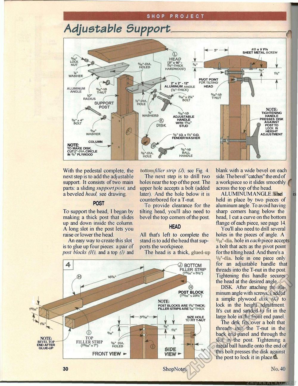
SHOP PROJECT Adjustable Support With the pedestal complete, the next step is to add the adjustable support. It consists of two main parts: a sliding support post, and a beveled head, see drawing. POST To support the head, I began by making a thick post that slides up and down inside the column. A long slot in the post lets you raise or lower the head. An easy way to create this slot is to glue up four pieces: a pair of post blocks (H), and a top (I) and filler strip (J), see Fig. 4. The next step is to drill two holes near the top ofthe post. The upper hole accepts a bolt (added later). And the hole below it is counterbored for a T-nut. To provide clearance for the tilting head, you'll also need to bevel the top corners ofthe post. HEAD All that's left to complete the stand is to add the head that supports the workpiece. The head is a thick, glued-up blank with a wide bevel on each side. The bevel "catches" the end of a workpiece so it slides smoothly f across the top of the head. ALUMINUM ANGLE.Fitted i held in place by two pieces of aluminum angle. To avoid having sharp corners hang below the head, I cut a curve on the bottom flange of each piece, see page 14. You'll also need to drill several holes in the pieces of angle. A 5/i6"-dia. hole in each piece accepts a bolt that acts as the pivot point for the tilting head. And there's a V2"-dia. hole in one piece only for an adjustable handle that threads into the T-nut in the post. Tightening this handle secures the head at the desired angle. DISK. After attaching the aluminum angle with screws, I added a simple plywood disk (K) to lock in the height adjustment. It's cut and sanded to fit in the large hole in the front end panel. The disk fits over a bolt that threads into the T-nut in the back end panel and through the slot in the post. Tightening a metal ball handle onto the end of this bolt presses the disk against the post to lock it in placed 28 ShopNotes 40 |


