77 - Sliding Door Shop Cabinet, страница 20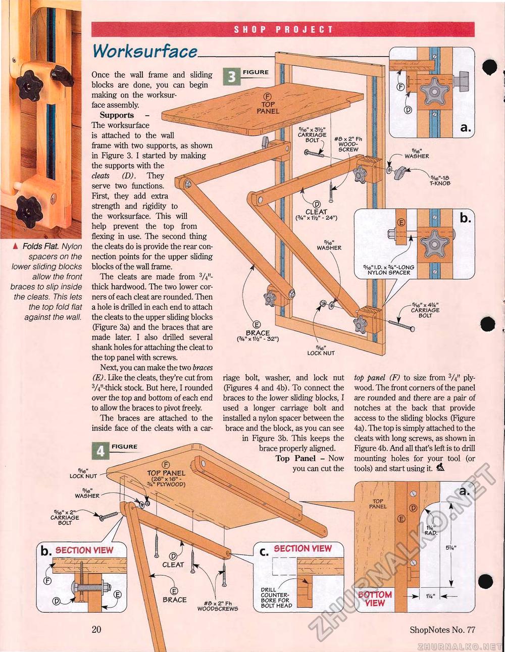
WorksurfaceOnce the wall frame and sliding blocks are done, you can begin making on the worksur-face assembly. Supports - Ej^S^-Ic^ Hie worksurface is attached to the wall frame with two supports, as shown in Figure 3. I started by making the supports with the cleats (D). They serve two functions. UJP First, they add extra \\ \ strength and rigidity to \\ the worksurface. This will help prevent the top from flexing in use. The second thing the cleats do is provide the rear connection points for the upper sliding blocks of the wall frame. The cleats are made from 3/4M-thick hardwood. The two lower corners of each cleat are rounded. Then a hole is drilled in each end to attach the cleats to the upper sliding blocks (Figure 3a) and the braces that are made later. I also drilled several shank holes for attaching the cleat to the top panel with screws. Next, you can make the two braces (E). Like the cleats, they're cut from 3/4M-thick stock. But here, I rounded over the top and bottom of each end to allow the braces to pivot freely. The braces are attached to the inside face of the cleats with a car- TOP PANEL 5/l«" X 3'/2" CARRIAGE BOLT -n #0 x 2" Fh WOOD-SCREW WASHER T-KNOB CLEAT (%" x W - 24") I Folds Flat. Nylon spacers on the lower sliding blocks allow the front braces to slip inside the cleats. This lets the top fold flat against the wall. WASHER 5/ie" I.D. x %"-LONG NYLON SPACER -5Ae"x4'/t" CARRIAGE BOLT LOCK NUT top panel (F) to size from plywood. The front corners of the panel are rounded and there are a pair of notches at the back that provide access to the sliding blocks (Figure 4a). The top is simply attached to the cleats with long screws, as shown in Figure 4b. And all thafs left is to drill mounting holes for your tool (or tools) and start using it. riage bolt, washer, and lock nut (Figures 4 and 4b). To connect the braces to the lower sliding blocks, I used a longer carriage bolt and installed a nylon spacer between the brace and the block, as you can see in Figure 3b. This keeps the brace properly aligned. Top Panel - Now you can cut the TOP PANEL (26" x 16" -44' PLYWOOD) LOCK NUT 5/)6" WASHER TOP PANEL 5/ie" x 2"'' CARRIAGE BOLT SECTION VIEW b. SECTION VIEW DRILL COUNTER-BORE FOR BOLT HEAD BOTTOM VIEW #& x 2" Fh WOODSCREWS ShopNotes No. 77 < |


