Woodworker's Journal 101-Projects-for-Woodworkers, страница 243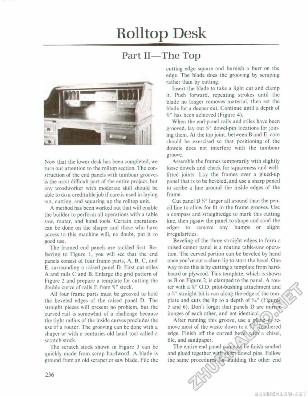
Rolltop DeskPart II Now that the lower desk has been completed, we turn our attention to the rolltop section. The construction of the end panels with tambour grooves is the most difficult part of the entire project, but any woodworker with moderate skill should be able to do a creditable job if care is used in laying out, cutting, and squaring up the rolltop unit. A method has been worked out that will enable the builder to perform all operations with a table saw, router, and hand tools. Certain operations can be done on the shaper and those who have access to this machine will, no doubt, put it to good use. The framed end panels are tackled first. Referring to Figure 1, you will see that the end panels consist of four frame parts, A. B, C, and E. surrounding a raised panel D, First cut stiles A and rails C and B. Enlarge the grid pattern of Figure 2 and prepare a template for cutting the double curve of rails E from %" stock. All four frame parts must be grooved to hold the beveled edges of the raised panel D. The straight pieces will present no problem, but the curved rail is somewhat of a challenge because the tight radius of the inside curves precludes the use of a router. The grooving can be done with a shaper or with a centuries-old hand tool called a scratch stock. The scratch stock shown in Figure 3 can be quickly made from scrap hardwood. A blade is ground from an old scraper or saw blade. File the The Top cutting edge square and burnish a burr on the edge. The blade does the grooving by scraping rather than by cutting. Insert the blade to take a light cut and clamp it. Push forward, repeating strokes until the blade no longer removes material, then set the blade for a deeper cut. Continue until a depth of %" has been achieved (Figure 4). When the end-panel rails and stiles have been grooved, lay out %" dowel-pin locations for joining them. At the top joint, between B and E, care should be exercised so that positioning of the dowels does not interfere with the tambour groove. Assemble the frames temporarily with slightly loose dowels and check for squareness and well-fitted joints. Lay the frames over a glued-up panel that is to be beveled, and use a sharp pencil to scribe a line around the inside edges of the frame. Cut panel D larger all around than the pencil line to allow for fit in the frame grooves. Use a compass and straightedge to mark this cutting line, then jigsaw the panel to shape and sand the edges to remove any bumps or slight irregularities. Beveling of the three straight edges to form a raised center panel is a routine table-saw operation. The curved portion can be beveled by hand once you've cut a clean lip to start the bevel. One way to do this is by cutting a template from hard-board or plywood. This template, which is shown as B on Figure 2, is clamped to the panel. A router with a %'' O.D. pilot-bushing attachment and a straight bit is run along the edge of the template and cuts the lip to a depth of V\t," (Figures 5 and 6). Don't forget that panels D are mirror images of each other, and not identical. After running this groove, use a plane to remove most of the waste down to a feathered edge. Finish off the curved bevel with a chisel, file, and sandpaper. The entire end panel can now be finish sanded and glued together with short dowel pins, Follow the same procedures for building the other end 236 |


