Woodworker's Journal 1984-8-5, страница 52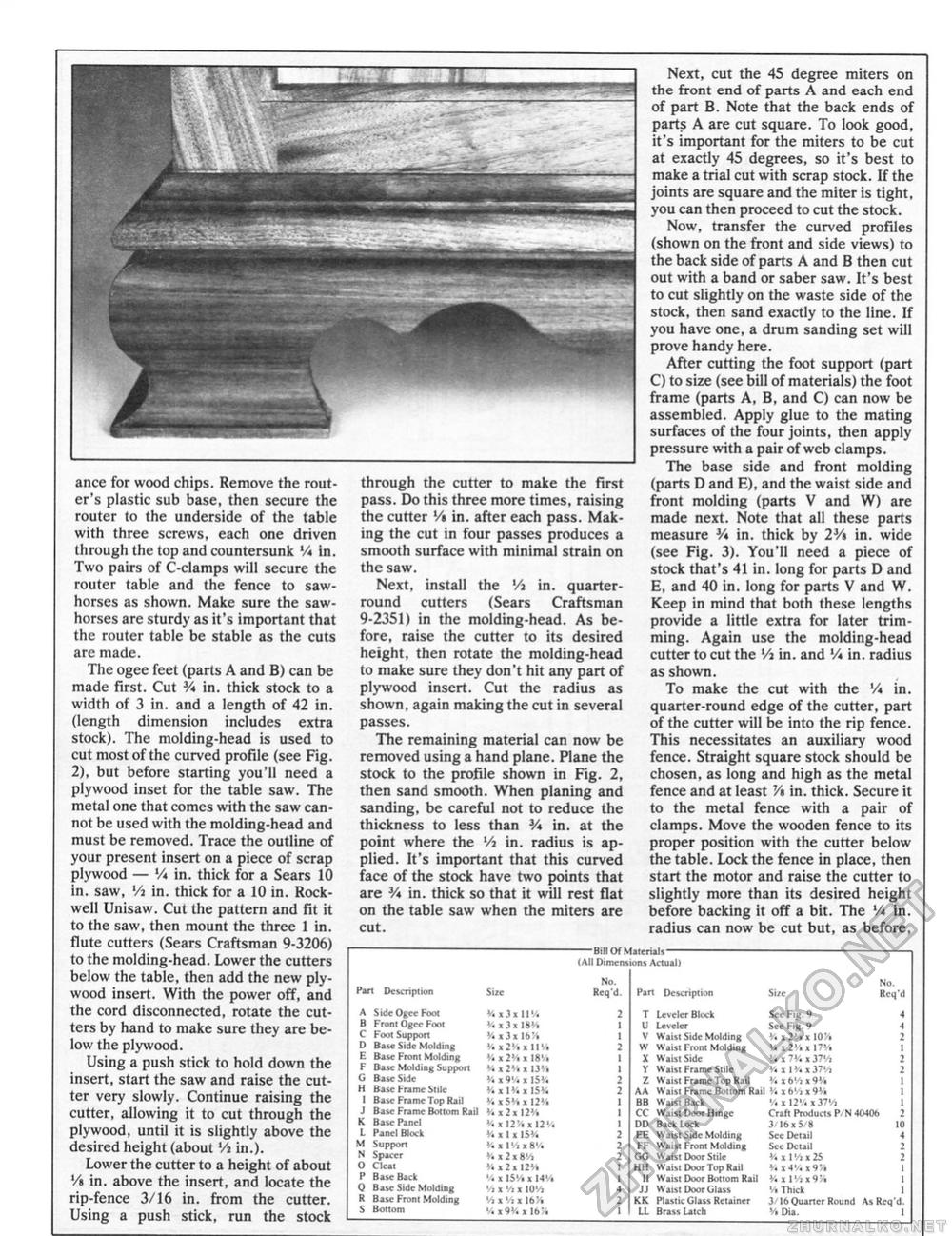
ance for wood chips. Remove the router's plastic sub base, then secure the router to the underside of the table with three screws, each one driven through the top and countersunk V* in. Two pairs of C-clamps will secure the router table and the fence to saw-horses as shown. Make sure the saw-horses are sturdy as it's important that the router table be stable as the cuts are made. The ogee feet (parts A and B) can be made first. Cut 3A in. thick stock to a width of 3 in. and a length of 42 in. (length dimension includes extra stock). The molding-head is used to cut most of the curved profile (see Fig. 2), but before starting you'll need a plywood inset for the table saw. The metal one that comes with the saw cannot be used with the molding-head and must be removed. Trace the outline of your present insert on a piece of scrap plywood — V* in. thick for a Sears 10 in. saw, lA in. thick for a 10 in. Rockwell Unisaw. Cut the pattern and fit it to the saw, then mount the three 1 in. flute cutters (Sears Craftsman 9-3206) to the molding-head. Lower the cutters below the table, then add the new plywood insert. With the power off, and the cord disconnected, rotate the cutters by hand to make sure they are below the plywood. Using a push stick to hold down the insert, start the saw and raise the cutter very slowly. Continue raising the cutter, allowing it to cut through the plywood, until it is slightly above the desired height (about 'A in.). Lower the cutter to a height of about '/( in. above the insert, and locate the rip-fence 3/16 in. from the cutter. Using a push stick, run the stock through the cutter to make the first pass. Do this three more times, raising the cutter '/« in. after each pass. Making the cut in four passes produces a smooth surface with minimal strain on the saw. Next, install the Vi in. quarter-round cutters (Sears Craftsman 9-2351) in the molding-head. As before, raise the cutter to its desired height, then rotate the molding-head to make sure they don't hit any part of plywood insert. Cut the radius as shown, again making the cut in several passes. The remaining material can now be removed using a hand plane. Plane the stock to the profile shown in Fig. 2, then sand smooth. When planing and sanding, be careful not to reduce the thickness to less than V* in. at the point where the Vt in. radius is applied. It's important that this curved face of the stock have two points that are V* in. thick so that it will rest flat on the table saw when the miters are cut. Next, cut the 45 degree miters on the front end of parts A and each end of part B. Note that the back ends of parts A are cut square. To look good, it's important for the miters to be cut at exactly 45 degrees, so it's best to make a trial cut with scrap stock. If the joints are square and the miter is tight, you can then proceed to cut the stock. Now, transfer the curved profiles (shown on the front and side views) to the back side of parts A and B then cut out with a band or saber saw. It's best to cut slightly on the waste side of the stock, then sand exactly to the line. If you have one, a drum sanding set will prove handy here. After cutting the foot support (part C) to size (see bill of materials) the foot frame (parts A, B, and C) can now be assembled. Apply glue to the mating surfaces of the four joints, then apply pressure with a pair of web clamps. The base side and front molding (parts D and E), and the waist side and front molding (parts V and W) are made next. Note that all these parts measure V* in, thick by 2V* in. wide (see Fig. 3). You'll need a piece of stock that's 41 in. long for parts D and E, and 40 in. long for parts V and W. Keep in mind that both these lengths provide a little extra for later trimming. Again use the molding-head cutter to cut the Vj in. and '/* in. radius as shown. To make the cut with the V* in, quarter-round edge of the cutter, part of the cutter will be into the rip fence. This necessitates an auxiliary wood fence. Straight square stock should be chosen, as long and high as the metal fence and at least V* in. thick. Secure it to the metal fence with a pair of clamps. Move the wooden fence to its proper position with the cutter below the table. Lock the fence in place, then start the motor and raise the cutter to slightly more than its desired height before backing it off a bit. The V* in. radius can now be cut but, as before, -Bill Of Materials- {All Dimensions Actual I Part Description A Side Ogee Foot B Front Ogee Fool C Foot Support D Base Side Molding E Base Front Molding F Base Molding Support G Base Side H Base Frame Stile 1 Base Frame Top Rail J Base Frame Bottom Rail K Base Panel L Panel Block M Support N Spacer O Cleat P Base Back Q Base Side Molding K Base From Molding S Bottom Size V. x3 a 11 v. 131 IK'. % i 3 x ]<>% '/. x 2M111'/. % x 2% x 18'/. V. x 2*4 x 13% V, X 9V, X IS*. y. x ivi x i5w V. xSHx 12% a 12112'/. V. X 12% x 12W W x 1 x 15% Vi x 1 Vi i SV. V. i2i0'i % x2H2% '. x IStt x 14'/. Vi X '/I i 10'/, */> x '/i x 16% MjW x it;. No. Req'd. Part Description Si/e No. Req'd T U v w X Y z AA BB CC DD TIFF CO HH II JJ KK U Lcveler Block Leveler Waist Side Molding Waist Front Molding Waisi Side Waist Frame Stile Waist Frame Top Rail Waisi Frame Bottom Rail Waist Back Waist Door Hinge Back lock Waist Side Molding Waist Front Molding Waisi Door Stile Waist Door Top Rail Waist Door Bottom Rail Waist Door Glass Plastic Glass Retainer Brass Latch See Fig. t See Fig.9 y. % 2V» I 10% y. x2'/. i 17% y. x IV, 137'/i y. x i y.«j7w y. x ti'/i 19% y. > 6'/i 19% '/. X 12'/. > 3?'/t Craft Products P/N 40(06 3/10x5/8 10 Sec Detail See Detail % xl'/n2S y. i4M x9% y. x l'/»x9% % Thick 3 16 Quarter Round As Req'd. % Dia. I |


