Woodworker's Journal 1984-8-5, страница 55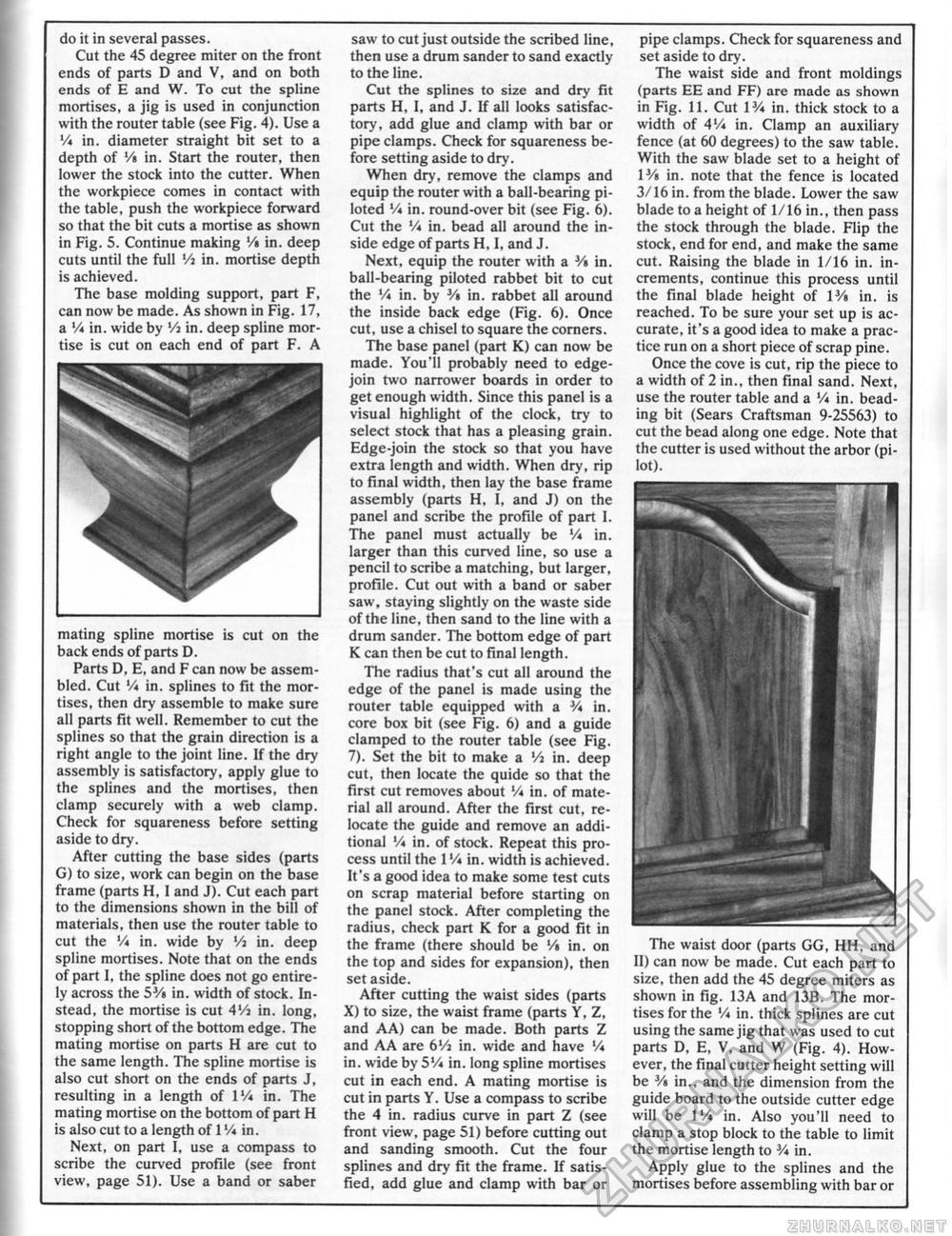
do it in several passes. Cut the 45 degree miter on the front ends of parts D and V, and on both ends of E and W. To cut the spline mortises, a jig is used in conjunction with the router table (see Fig. 4). Use a V* in. diameter straight bit set to a depth of '/« in. Start the router, then lower the stock into the cutter. When the workpiece comes in contact with the table, push the workpiece forward so that the bit cuts a mortise as shown in Fig. 5. Continue making '/• in. deep cuts until the full Vi in. mortise depth is achieved. The base molding support, part F, can now be made. As shown in Fig. 17, a Vi in. wide by Vi in. deep spline mortise is cut on each end of part F. A mating spline mortise is cut on the back ends of parts D. Parts D, E, and F can now be assembled. Cut '/* in. splines to fit the mortises, then dry assemble to make sure all parts fit well. Remember to cut the splines so that the grain direction is a right angle to the joint line. If the dry assembly is satisfactory, apply glue to the splines and the mortises, then clamp securely with a web clamp. Check for squareness before setting aside to dry. After cutting the base sides (parts G) to size, work can begin on the base frame (parts H, I and J). Cut each part to the dimensions shown in the bill of materials, then use the router table to cut the Vi in. wide by Vi in. deep spline mortises. Note that on the ends of part I, the spline does not go entirely across the 5J/i in. width of stock. Instead, the mortise is cut 4'/i in. long, stopping short of the bottom edge. The mating mortise on parts H are cut to the same length. The spline mortise is also cut short on the ends of parts J, resulting in a length of IVi in. The mating mortise on the bottom of part H is also cut to a length of 1Vi in. Next, on part 1, use a compass to scribe the curved profile (see front view, page 51). Use a band or saber saw to cut just outside the scribed line, then use a drum sander to sand exactly to the line. Cut the splines to size and dry fit parts H, 1, and J. If all looks satisfactory, add glue and clamp with bar or pipe clamps. Check for squareness before setting aside to dry. When dry, remove the clamps and equip the router with a ball-bearing piloted Vi in. round-over bit (see Fig. 6). Cut the Vi in. bead all around the inside edge of parts H, I, and J. Next, equip the router with a V» in. ball-bearing piloted rabbet bit to cut the V* in. by Vi in. rabbet all around the inside back edge (Fig. 6). Once cut, use a chisel to square the corners. The base panel (part K) can now be made. You'll probably need to edge-join two narrower boards in order to get enough width. Since this panel is a visual highlight of the clock, try to select stock that has a pleasing grain. Edge-join the stock so that you have extra length and width. When dry, rip to final width, then lay the base frame assembly (parts H, I, and J) on the panel and scribe the profile of part 1. The panel must actually be Vi in. larger than this curved line, so use a pencil to scribe a matching, but larger, profile. Cut out with a band or saber saw, staying slightly on the waste side of the line, then sand to the line with a drum sander. The bottom edge of part K can then be cut to final length. The radius that's cut all around the edge of the panel is made using the router table equipped with a 3A in. core box bit (see Fig. 6) and a guide clamped to the router table (see Fig. 7). Set the bit to make a Vi in. deep cut, then locate the quide so that the first cut removes about V* in. of material all around. After the first cut, relocate the guide and remove an additional Vi in. of stock. Repeat this process until the I'A in. width is achieved. It's a good idea to make some test cuts on scrap material before starting on the panel stock. After completing the radius, check part K for a good fit in the frame (there should be '/« in. on the top and sides for expansion), then set aside. After cutting the waist sides (parts X) to size, the waist frame (parts V, Z, and A A) can be made. Both parts Z and A A are 6'A in. wide and have V* in. wide by 5% in. long spline mortises cut in each end. A mating mortise is cut in parts Y. Use a compass to scribe the 4 in. radius curve in part Z (see front view, page 51) before cutting out and sanding smooth. Cut the four splines and dry fit the frame. If satisfied, add glue and clamp with bar or pipe clamps. Check for squareness and set aside to dry. The waist side and front moldings (parts EE and FF) are made as shown in Fig. 11. Cut VA in. thick stock to a width of 4Vi in. Clamp an auxiliary fence (at 60 degrees) to the saw table. With the saw blade set to a height of Wt in. note that the fence is located 3/16 in. from the blade. Lower the saw blade to a height of 1/16 in,, then pass the stock through the blade, Flip the stock, end for end, and make the same cut. Raising the blade in 1/16 in. increments, continue this process until the final blade height of V/% in. is reached. To be sure your set up is accurate, it's a good idea to make a practice run on a short piece of scrap pine. Once the cove is cut, rip the piece to a width of 2 in., then final sand. Next, use the router table and a Vi in. beading bit (Sears Craftsman 9-25563) to cut the bead along one edge. Note that the cutter is used without the arbor (pilot). The waist door (parts GG, HH, and II) can now be made. Cut each part to size, then add the 45 degree miters as shown in fig. 13A and 13B. The mortises for the 'A in. thick splines are cut using the same jig that was used to cut parts D, E, V. and W (Fig. 4). However, the final cutter height setting will be 3A in., and the dimension from the guide board to the outside cutter edge will be IVi in. Also you'll need to clamp a stop block to the table to limit the mortise length to 3A in. Apply glue to the splines and the mortises before assembling with bar or |


