Woodworker's Journal 1984-8-5, страница 56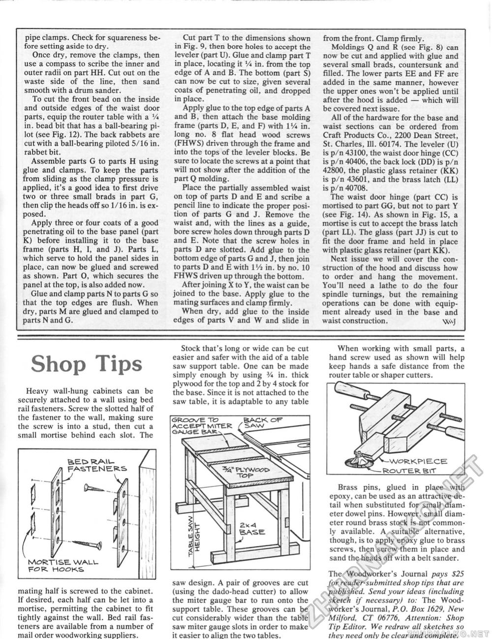
pipe clamps. Check for squareness before setting aside to dry. Once dry, remove the clamps, then use a compass to scribe the inner and outer radii on part HH. Cut out on the waste side of the line, then sand smooth with a drum sander. To cut the front bead on the inside and outside edges of the waist door parts, equip the router table with a Vi in. bead bit that has a ball-bearing pilot (see Fig. 12). The back rabbets are cut with a ball-bearing piloted 5/16 in. rabbet bit. Assemble parts G to parts H using glue and clamps. To keep the parts from sliding as the clamp pressure is applied, it's a good idea to first drive two or three small brads in part G, then clip the heads off so 1/16 in. is exposed. Apply three or four coats of a good penetrating oil to the base panel (part K) before installing it to the base frame (parts H, I, and J). Parts L, which serve to hold the panel sides in place, can now be glued and screwed as shown. Part 0, which secures the panel at the top, is also added now. Glue and clamp parts N to parts G so that the top edges are flush. When dry, parts M are glued and clamped to parts N and G. Cut part T to the dimensions shown in Fig. 9, then bore holes to accept the leveler (part U). Glue and clamp part T in place, locating it Vi in. from the top edge of A and B. The bottom (part S) can now be cut to size, given several coats of penetrating oil, and dropped in place. Apply glue to the top edge of parts A and B, then attach the base molding frame (parts D, E, and F) with IVi in. long no. 8 flat head wood screws (FHWS) driven through the frame and into the tops of the leveler blocks. Be sure to locate the screws at a point that will not show after the addition of the part Q molding. Place the partially assembled waist on top of parts D and E and scribe a pencil line to indicate the proper position of parts G and J. Remove the waist and, with the lines as a guide, bore screw holes down through parts D and E. Note that the screw holes in parts D are slotted. Add glue to the bottom edge of parts G and J, then join to parts D and E with 1 'A in. by no. 10 FHWS driven up through the bottom. After joining X to Y, the waist can be joined to the base. Apply glue to the mating surfaces and clamp firmly. When dry, add glue to the inside edges of parts V and W and slide in from the front. Clamp firmly. Moldings Q and R (see Fig. 8) can now be cut and applied with glue and several small brads, countersunk and filled. The lower parts EE and FF are added in the same manner, however the upper ones won't be applied until after the hood is added — which will be covered next issue. All of the hardware for the base and waist sections can be ordered from Craft Products Co., 2200 Dean Street, St. Charles, III. 60174. The leveler (U) is p/n 43100, the waist door hinge (CC) is p/n 40406, the back lock (DD) is p/n 42800, the plastic glass retainer (KK) is p/n 43601, and the brass latch (LL) is p/n 40708. The waist door hinge (part CC) is mortised to part GG, but not to part Y (see Fig. 14). As shown in Fig. 15, a mortise is cut to accept the brass latch (part LL). The glass (part JJ) is cut to fit the door frame and held in place with plastic glass retainer (part KK). Next issue we will cover the construction of the hood and discuss how to order and hang the movement. You'll need a lathe to do the four spindle turnings, but the remaining operations can be done with equipment already used in the base and waist construction. Wvj Shop Tips Heavy wall-hung cabinets can be securely attached to a wall using bed rail fasteners. Screw the slotted half of the fastener to the wall, making sure the screw is into a stud, then cut a small mortise behind each slot. The A FASTE.NE.R-S> ftsimm. _ L 5 MORTISE. WALL FOR HOOKS V f- f V •I mating half is screwed to the cabinet. If desired, each half can be let into a mortise, permitting the cabinet to fit tightly against the wall. Bed rail fasteners are available from a number of mail order woodworking suppliers. Stock that's long or wide can be cut easier and safer with the aid of a table saw support table. One can be made simply enough by using V* in. thick plywood for the top and 2 by 4 stock for the base. Since it is not attached to the saw table, it is adaptable to any table saw design. A pair of grooves are cut (using the dado-head cutter) to allow the miter gauge bar to run onto the support table. These grooves can be cut considerably wider than the table saw miter gauge slots in order to make it easier to alien the two tables. When working with small parts, a hand screw used as shown will help keep hands a safe distance from the router table or shaper cutters. Brass pins, glued in place with epoxy, can be used as an attractive detail when substituted for small diameter dowel pins. However, small diameter round brass stock is not commonly available, A suitable alternative, though, is to apply epoxy glue to brass screws, then screw them in place and sand the heads off with a belt sander. The Woodworker's Journal pays S25 for reader-submitted shop tips that are published. Send your ideas (including sketch if necessary) to: The Woodworker's Journal, P.O. Box 1629, New Milford. CT 06776, Attention: Shop Tip Editor. We redraw all sketches so they need only be clear and complete. |


