Woodworker's Journal 1985-9-1, страница 52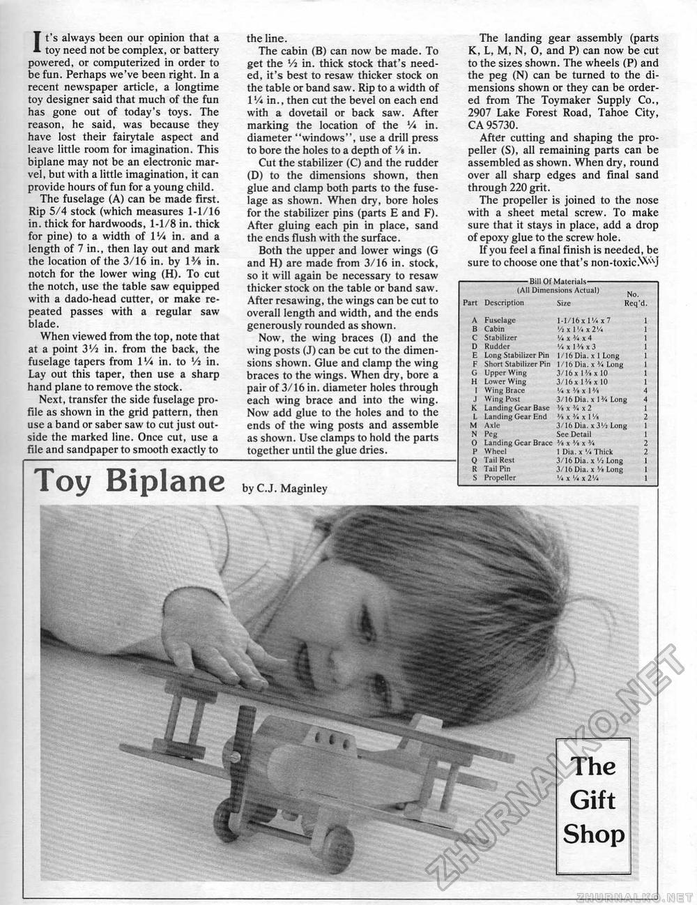
The landing gear assembly (parts K, L, M, N, 0, and P) can now be cut to the sizes shown. The wheels (P) and the peg (N) can be turned to the dimensions shown or they can be ordered from The Toy maker Supply Co., 2907 Lake Forest Road, Tahoe City, CA 95730. After cutting and shaping the propeller (S), all remaining parts can be assembled as shown. When dry, round over all sharp edges and final sand through 220 grit. The propeller is joined to the nose with a sheet metal screw. To make sure that it stays in place, add a drop of epoxy glue to the screw hole. If you feel a final finish is needed, be sure to choose one that's non-toxicNv^J -Bill Of Materials- (AI1 Dimension!, Actual] -Bill Of Materials- (AI1 Dimension!, Actual]
It's always been our opinion that a toy need not be complex, or battery powered, or computerized in order to be fun. Perhaps we've been right. In a recent newspaper article, a longtime toy designer said that much of the fun has gone out of today's toys. The reason, he said, was because they have lost their fairytale aspect and leave little room for imagination. This biplane may not be an electronic marvel, but with a little imagination, it can provide hours of fun for a young child. The fuselage (A) can be made first. Rip 5/4 stock (which measures 1-1/16 in. thick for hardwoods, 1-1/8 in. thick for pine) to a width of 1V* in. and a length of 7 in,, then lay out and mark the location of the 3/16 in, by l3/» in, notch for the lower wing (H). To cut the notch, use the table saw equipped with a dado-head cutter, or make repeated passes with a regular saw blade. When viewed from the top, note that at a point 3Vi in. from the back, the fuselage tapers from IV* in. to Vi in. Lay out this taper, then use a sharp hand plane to remove the stock. Next, transfer the side fuselage profile as shown in the grid pattern, then use a band or saber saw to cut just outside the marked line. Once cut, use a file and sandpaper to smooth exactly to Toy Biplane the line. The cabin (B) can now be made. To get the Vi in. thick stock that's needed, it's best to resaw thicker stock on the table or band saw. Rip to a width of 1V* in., then cut the bevel on each end with a dovetail or back saw. After marking the location of the V* in. diameter "windows", use a drill press to bore the holes to a depth of Vt in. Cut the stabilizer (C) and the rudder (D) to the dimensions shown, then glue and clamp both parts to the fuselage as shown. When dry, bore holes for the stabilizer pins (parts E and F). After gluing each pin in place, sand the ends flush with the surface. Both the upper and lower wings (G and H) are made from 3/16 in. stock, so it will again be necessary to resaw thicker stock on the table or band saw. After resawing, the wings can be cut to overall length and width, and the ends generously rounded as shown. Now, the wing braces (I) and the wing posts (J) can be cut to the dimensions shown. Glue and clamp the wing braces to the wings. When dry, bore a pair of 3/16 in. diameter holes through each wing brace and into the wing. Now add glue to the holes and to the ends of the wing posts and assemble as shown. Use clamps to hold the parts together until the glue dries. by C.J. Maginley |
||||||||||||||||||||||||||||||||||||||||||||||||||||||||||||||||||||||||||||||||


