Woodworker's Journal 1985-9-2, страница 33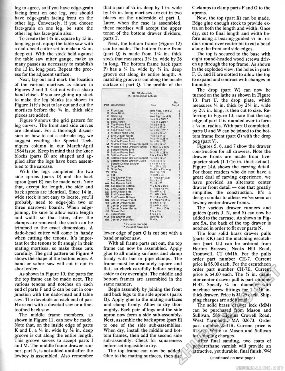
leg to agree, so if you have edge-grain facing front on one leg, you should have edge-grain facing front on the other leg. Conversely, if you choose face-grain on one leg, be sure the other leg has face-grain also. To create the l3A in. square by 13 in. long leg post, equip the table saw with a dado-head cutter set to make a V* in. deep cut. With the stock held against the table saw miter gauge, make as many passes as necessary to establish the 13 in. long post. Repeat the process for the adjacent surface. Next, lay out and mark the location of the various mortises as shown in Figures 2 and 3. Cut out with a sharp hand chisel. If you are gluing up stock to make the leg blanks (as shown in Figure 1) it's best to lay out and cut the mortises before the 3A in. thick side pieces are added. Figure 9 shows the grid pattern for leg curves. The front and side curves are identical. For a thorough discussion on how to cut a cabriole leg, we suggest reading the Special Techniques column in our March/April 1984 issue. Keep in mind that the knee blocks (parts B) are shaped and applied after the legs have been assembled to the carcase. With the legs completed the two side aprons (parts D) and the back apron (part E) can be made next. Note that, except for length, the side and back aprons are identical. Since 14 in. wide stock is not easy to locate, you'll probably need to edge-join two or three narrower boards. When edge-joining, be sure to allow extra length and width so that later, after the clamps are removed, the stock can be trimmed to the exact dimensions. A dado-head cutter will come in handy when cutting the tenons. It's important for the tenons to fit snugly in their mating mortises, so make these cuts carefully. The grid pattern on Figure 9 shows the shape of the bottom edge. A band or saber saw will cut it out in short order. As shown in Figure 10, the parts for the top frame can be made next. The various tenons and notches on each end of parts F and G can be cut in conjunction with the dado-head and table saw. The dovetails on each end of part H are cut with a dovetail saw or a fine-toothed back saw. The middle frame members, as shown in Figure 11, can now be made. Note that, on the inside edge of parts K and L, a V* in. wide by 3/« in. deep groove is cut along the entire length. This groove serves to accept parts I and M. The middle frame drawer runner, part N, is not added until after the lowboy is assembled. Also remember that a pair of V* in. deep by 1 in. wide by lVs in. long mortises are cut in two places on the underside of part L. Later, when the case is assembled, these mortises will accept the upper tenon of the bottom drawer dividers, parts T. Next, the bottom frame (Figure 12) can be made. The bottom frame front (part Q) is made from IV* in. thick stock that measures 3'A in. wide by 28 in long. The bottom frame back (part P) has a V* in. wide by 3/s in. deep groove cut along its entire length. A matching groove is cut along the inside surface of part Q. The profile of the
lower edge of part Q is cut out with a band or saber saw. With all frame parts cut out, the top frame can now be assembled. Apply glue to all mating surfaces and clamp firmly with bar or pipe clamps. The frame must be absolutely square and flat, so check carefully before setting aside to dry overnight. The middle and bottom frames are assembled in the same manner. Begin assembly by joining the front and back legs to the side aprons (parts D). Apply glue to the mating surfaces and clamp firmly. Allow to dry thoroughly. Each pair of legs and the side apron now form a side sub-assembly. Next, assemble the back apron (part E) to one of the side sub-assemblies. When dry, install the middle and bottom frames, then add the second side sub-assembly. Check for squareness before setting aside to dry. The top frame can now be added. Glue to the mating surfaces, then use C-clamps to clamp parts F and G to the aprons. Now, the top (part X) can be made. Edge glue enough stock to provide extra on both the length and width. Once dry, cut to final length and width before using a bearing-guided Vi in. radius round-over router bit to cut a bead along the front and side edges. The top is secured to the base with eight round-headed wood screws driven up through the top frame. As shown in the exploded view, the holes in parts F, G, and H are slotted to allow the top to expand and contract with changes in humidity. The drop (part W) can now be turned on the lathe as shown in Figure 13. Part U, the drop plate, which measures Vi in. thick by 2V* in. wide by 2V4 in. long, is then cut to size. Referring to Figure 13, note that the top edge of part U is rounded over to form a V* in. radius. With part U completed, parts U and W can be joined to the bottom frame front (part Q) with the drop peg (part V). Figures 5, 6, and 7 show the drawer construction for all drawers. Note the drawer fronts are made from five-quarter stock (1-1/16 in. thick actual). Figure 14A shows the carving detail. For those readers who do not have a great deal of carving experience, we have provided an alternate center drawer front detail — one that greatly simplifies the construction. It's a design similar to others we've seen on lowboy center drawer fronts. The various drawer runners and guides (parts J, N, and S) can now be added to the carcase. As shown in Figure 5A, the back of the top drawer is notched in order to fit over parts N. The four solid brass drawer pulls (parts KK) and the matching escutcheon (part LL) can be ordered from Horton Brasses, Nooks Hill Road, Cromwell, CT 06416. For the pulls order part number CH-7. Current price is $5.00 each. For the escutcheon order part number CH-7E. Current price is $4.00 each. The 3A in. diameter center drawer pull is part number H-42. Specify V* in. diameter with machine screw fittings for 1-1/16 in. thick drawer. Price is $1.25 each. Shipping charges are additional. The solid brass drawer lock (MM) can be purchased from Mason and Sullivan, 586 Higgins Crowell Road, West Yarmouth, MA 02673. Order part number 253IB. Current price is $13.65. Write to Mason and Sullivan for shipping charges. After final sanding, two coats of polyurethane varnish will provide an attractive, yet durable, final finish. W<J (continued on next page) |
||||||||||||||||||||||||||||||||||||||||||||||||||||||||||||||||||||||||||||||||||||||||||||||||||||||||||||||||||||||||||||||||||||||||||||||||||||||||||||||||||||||||||||||||||||||||


