Woodworker's Journal 1985-9-6, страница 40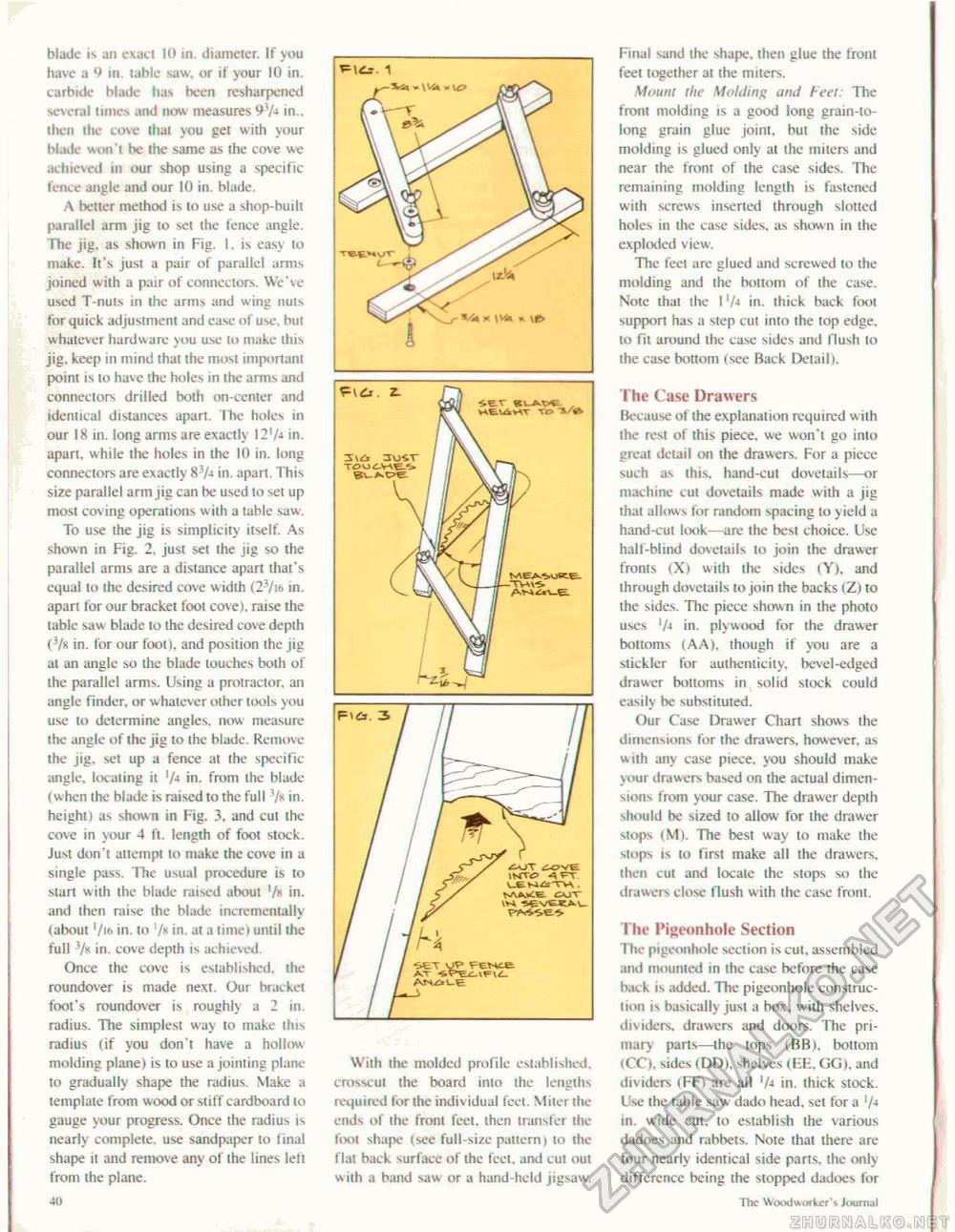
blade is an exaci 10 in. diameter. If you have a 9 in. table saw. or if your 10 in. carbide blade has been resharpened several limes and now measures 97-* in., then the cove thai you get with your blade won't be the same as the cove we achieved in our shop using a specific fence angle and our 10 in. blade. A better method is to use a shop-built parallel arm jig lo set the fence angle. The jig. as shown in Fig. t, is easy to make. It's jusl a pair of parallel arms joined with a pair of connectors. We've used T-nuls in ihe arms and wing nuls for quick adjustment and ease of use. hul whatever hardware you use to make this jig. keep in mind that the most important point is to have the holes in the arms and connectors drilled both on-center and ideniical distances apart. Ihe holes in our 18 in. long arms are exactly I2'A in. apart, while the holes in the 10 in. long connectors are exactly 8-7* in. apart. This size parallel arm jig can be used lo set up most coving operations with a table saw. To use the jig is simplicity itself. As shown in Fig. 2, just set the jig so the parallel arms are a distance apart that's equal to the desired cove w idth (2-7i<> in. aparl lor our bracket foot cove), raise the table saw blade to the desired cove depth (3/s in. for our fool), and position ihe jig at an angle so the blade touches both of the parallel arms. Using a protractor, an angle finder, or whatever other tools you use lo determine angles, now measure the angle of ihe jig to ihe blade. Remove the jig, set up a fence at the specific angle, locating it in. from the blade (when the blade is raised to the full 7* in. height) as shown in Fig. 3, and cut the cove in your 4 ft. length of foot stock. Just don't attempl to make the cove in a single pass. The usual procedure is to start with the blade raised about 7» in. and then raise the blade incrementally (about '/i6 in. to 7* in. at a time) until the full -7k in. cove depth is achieved. Once the cove is established, the roundover is made next. Our bracket foot's roundover is roughly a 2 in. radius. The simplest way to make this radius (if you don't have a hollow molding plane) is to use a jointing plane to gradually shape the radius. Make a template from wood or stiff cardboard to gauge your progress. Once the radius is nearly complete, use sandpaper to final shape il and remove any of the lines left from ihe plane. 40 With the molded profile established, crosscut the board into the lengths required for the individual feet. Miter the ends of ihe front feet, then transfer the foot shape (see full-size pattern) to ihe Hal back surface of the feet, and cut out w ith a band saw or a hand-held jigsaw. Final sand the shape, then glue the front feet together at the miters. Mount the Molding and Feel: The front molding is a good long grain-to-long grain glue joint, but the side molding is glued only al ihe miters and near the front of the case sides. The remaining molding length is fastened with screws inserted through slotted holes in the case sides, as shown in the exploded view. The feel are glued and screwed to the molding and the bottom of the case. Note that the I 'A in. thick back toot support has a step cut into the top edge, to fit around ihe case sides and Hush to the case bottom (see Back Detail). The Case Drawers Because of ihe explanation required with ihe rest of this piece, we won't go into greal detail on the drawers. For a piece such as this, hand-cut dovetails—or machine cut dovetails made wilh a jig that allows for random spacing lo yield a hand-cut look—are the best choice. Use half-blind dovetails to join the drawer fronts (X) with the sides (Y), and through dovetails to join the backs (Zl to the sides. The piece shown in the photo uses 7-t in. plywood for the drawer bottoms (AA), though if you are a stickler for authenticity, bevel-edged drawer bottoms in solid stock could easily be substituted. Our Case Drawer Chart shows the dimensions for ihe drawers, however, as w ith any case piece, you should make your drawers based on the actual dimensions from your case. The drawer depth should be sized to allow for the drawer stops (M). The besi way to make the slops is to first make all ihe drawers, then cut and locate the stops so the drawers close flush with ihe case front. The Pigeonhole Section The pigeonhole section is cut. assembled and mounted in the case before the case back is added. The pigeonhole construction is basically just a box. w ith shelves, dividers, drawers and doors. The primary parts—ihe lops (BBl, bottom (CO. sides (DD), shelves (EE. GG), and do iders (FF) are all in. thick stock. Use the table saw dado head, set for a 7-t in. wide cut, to establish ihe various dadoes and rabbets. Note that there are four nearly identical side parts, the only difference being the stopped dadoes for The Woodworker's Journal |


