Woodworker's Journal fall-2008, страница 89
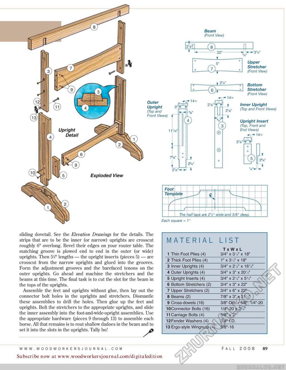
Each square = V Beam (Front View) ° Upper Stretcher ° (Front View) Bottom Stretcher (Front View) Inner Upright (Top and Front Weivsj Upright Insert (Top, Front and End WewsJ w, r- 14K Outer m"14" Upright 3"1- - (Top and Front Views) i M V 4) J 2V LU sliding dovetail. See the Elevation Drawings for the details. The strips that are to be the inner {or narrow) uprights are crosscut roughly 6" overlong. Bevel their edges on your router table. The matching groove is plowed end to end in the outer (or wide) uprights. Then 5:X" lengths — the upright inserts (pieces 5) — are crosscut from the narrow uprights and glued into the grooves. Form the adjustment grooves and the barefaced tenons on the outer uprights. Go ahead and machine the stretchers and the beams at this time. The final task is to cut the slot for the beam in the tops of the uprights. Assemble the feet and uprights without glue, then lay out the connector bolt holes in the uprights and stretchers. Dismantle these assemblies to drill the holes. Then glue up the feet and uprights. Bolt the stretchers to the appropriate uprights, and slide the inner assembly into the foot-and-wide-upright assemblies. Use the appropriate hardware (pieces 9 through 13) to assemble each horse. All that remains is to rout shallow dadoes in the beam and to set it into the slots in the uprights. Tally ho! &
Subscribe now at www.woodwoirkersjournal.com/digitaledition FALL 2008 89 |


