Creative Woodworks & crafts 1999-11, страница 23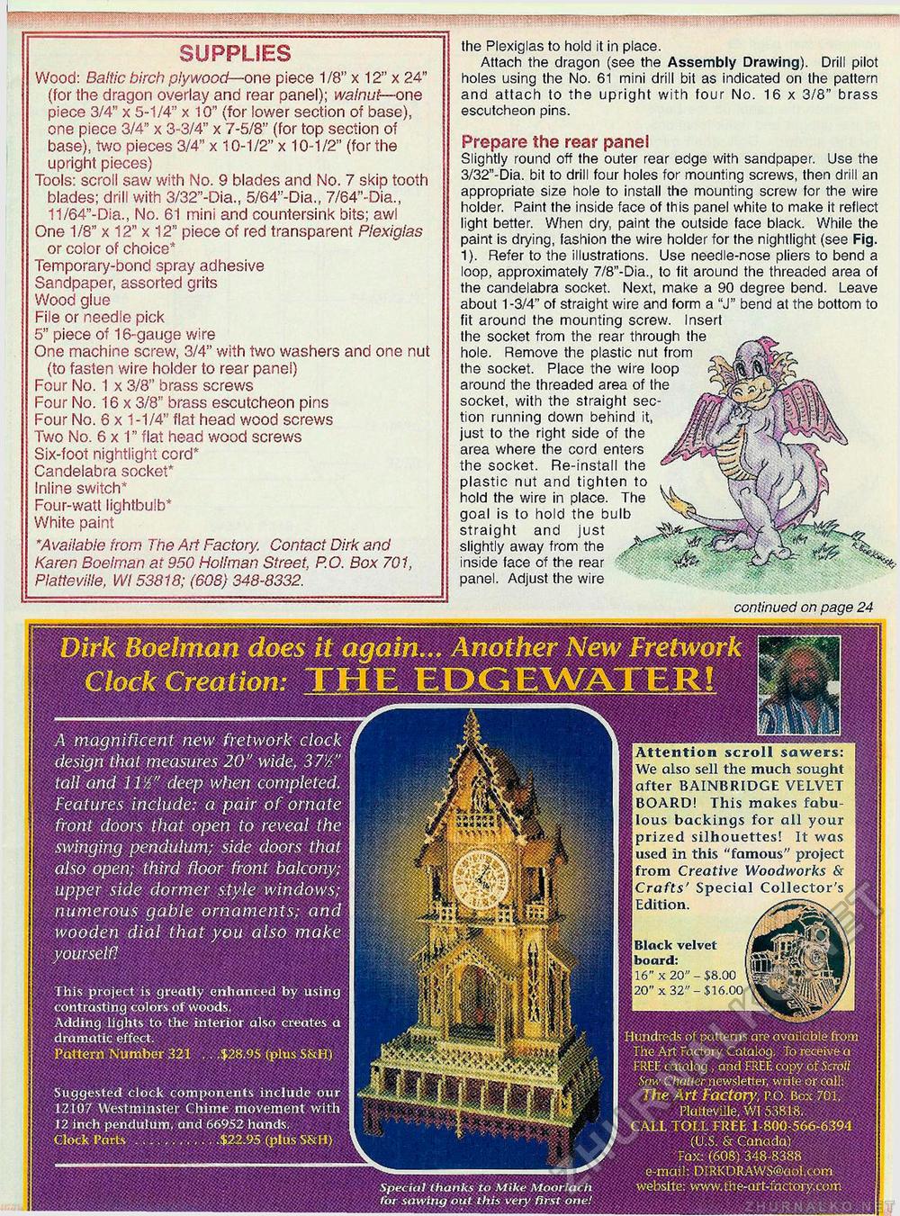
Dirk Boelman does it again... Another New Fretwork Clock Creation: THE EPGEWATER! 'A magnificent new fretwork clock design that measures 20" wide, 37'A" tall and 11'A" deep when completed. Features include: a pair of ornate front doors that open to reveal the swinging pendulum; side doors that also open; third floor front balcony; upper side dormer style windows; numerous gable ornaments; and wooden dial that you also make yourself! This project is greatly enhanced by using contrasting colors of woods. Adding lights to the interior also creates a dramatic effect. Pattern Number 321 .. .$28.95 (plus .S&H) Hundreds of patterns are available from The Art Factory Catalog. To receive a FREE catalog , and FREE copy of Saott Saw Chatter,newsletter, write or call; The Art Factory, P.O. Box 701, Plutteville, W1 53818. CALL TOLL FREE 1-800-566-6394 (US & Canada) Fax: (608). 348-8388 e-mail: DIRKDRAWS@aol.com website: www.the-art-factoiy.com Suggested clock components include our 12107 Westminster Chime movement with 12 inch pendulum, and 66952 hands. Clock Parts ........... .$22.95 (plus S&H) Special thanks to Mike Moorlach for sawing out this very first one! Attention scroll sawers: We also sell the much sought after BAINBRIDGE VELVET BOARD! This makes fabulous backings for all your prized silhouettes! It was used in this "famous" project from Creative Woodworks & Crafts' Special Collector's Edition. xiS^SSx f. «»<***: r ifM&ft- Black velvet board: 16" x 20" -$8.00 20" x 32"-$16.00 SUPPLIES Wood: Baltic birch plywood—one piece 1/8" x 12" x 24" (for the dragon overlay and rear panel); walnut— one piece 3/4" x 5-1/4" x 10" (for lower section of base), one piece 3/4" x 3-3/4" x 7-5/8" (for top section of base), two pieces 3/4" x 10-1/2" x 10-1/2" (for the upright pieces) Tools: scroll saw with No. 9 blades and No. 7 skip tooth blades; drill with 3/32"-Dia., 5/64"-Dia., 7/64"-Dia., 11/64"-Dia., No. 61 mini and countersink bits; awl One 1/8" x 12" x 12" piece of red transparent Plexiglas or color of choice* Temporary-bond spray adhesive Sandpaper, assorted grits Wood glue File or needle pick 5" piece of 16-gauge wire One machine screw, 3/4" with two washers and one nut (to fasten wire holder to rear panel) Four No. 1 x 3/8" brass screws Four No. 16 x 3/8" brass escutcheon pins Four No. 6 x 1-1/4" flat head wood screws Two No. 6 x 1" flat head wood screws Six-foot nightlight cord* Candelabra socket* Inline switch* Four-watt lightbulb* White paint *Available from The Ad Factory. Contact Dirk and Karen Boelman at 950 Holfman Street. P.O. Box 701, Piatteviile, Wl 53818; (608) 348-8332. the Plexiglas to hold it in place. Attach the dragon (see the Assembly Drawing). Drill pilot holes using the No. 61 mini drill bit as indicated on the pattern and attach to the upright with four No. 16 x 3/8" brass escutcheon pins. Prepare the rear panel Slightly round off the outer rear edge with sandpaper. Use the 3/32"-Dia. bit to drill four holes for mounting screws, then drill an appropriate size hole to install the mounting screw for the wire holder. Paint the inside face of this panel white to make it reflect light better. When dry, paint the outside face black. While the paint is drying, fashion the wire holder for the nightlight (see Fig. 1). Refer to the illustrations. Use needle-nose pliers to bend a loop, approximately 7/8"-Dia., to fit around the threaded area of the candelabra socket. Next, make a 90 degree bend. Leave about 1 -3/4" of straight wire and form a "J" bend at the bottom to fit around the mounting screw. Insert the socket from the rear through the hole. Remove the plastic nut from the socket. Place the wire loop around the threaded area of the socket, with the straight section running down behind it, just to the right side of the area where the cord enters the socket. Re-install the plastic nut and tighten to hold the wire in place. The goal is to hold the bulb straight and just slightly away from the . Jim inside face of the rear panel. Adjust the wire continued on page 24 |


