Creative Woodworks & crafts 2001-08, страница 60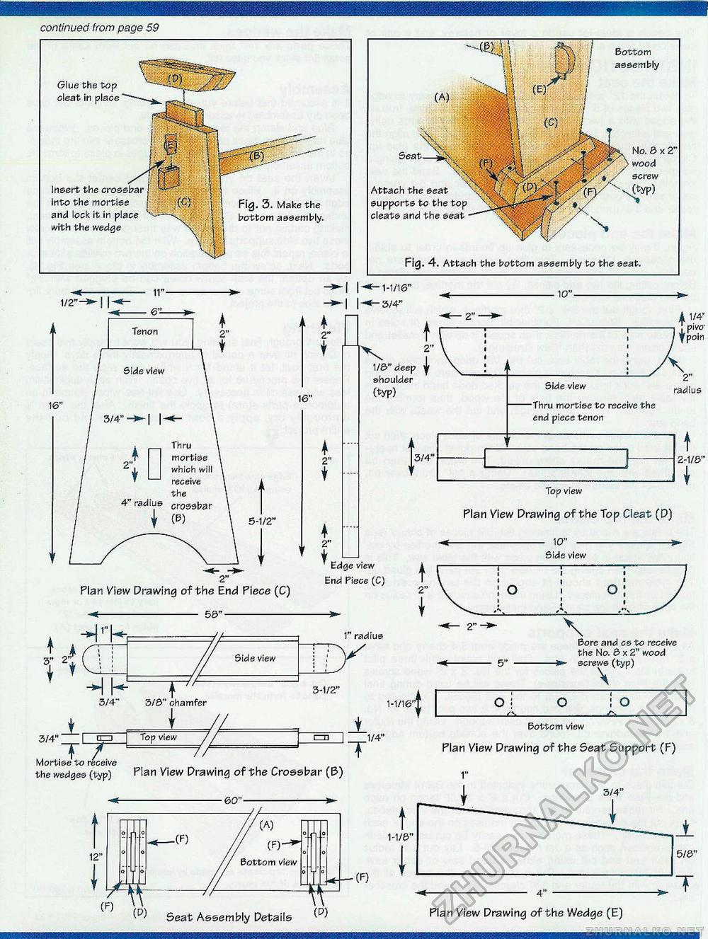
continued from page 59 Glue the top cleat in place Insert the into the mortise and lock it in place with the wedge Fig. 3. Make the bottom assembly. Fig. 4. Attach the bottom assembly to the seat. Attach the seat supports to the top cleats and the seat No. 6 x 2" wood screw Bottom assembly 2" 16" 5-1/2" 2" t 2" t •1-1/16" ■ 3/4" V f 1/8>" deep ^ shoulder (typ) . 10"- J3/4« Top view Plan View Drawing of the Top Cleat (D) 10" Side view Plan View Drawing of the End Piece (C) Edge view End Piece (C) o o; 56" t J 3" 2". + * ■*ir c -I Side view 1" radius \ 3-1/2" 3/4" 3/6" chamfer 1-1/16: 1 Bore and cs to receive the No. 6 x 2" wood -»- screws (typ) \ O ! : o _ 3/4" I 0=3 TJL Top view Mortise to receive the wedges (typ) Flan View Drawing of the Crossbar (B) T 1/4" Bottom view Plan View Drawing of the Seat Support (F) 1" J 3/4" 1-1/6" ■(F) Seat Assembly Details (p) Plan View Drawing of the Wedge (E) |


