Creative Woodworks & crafts 2003-03, страница 51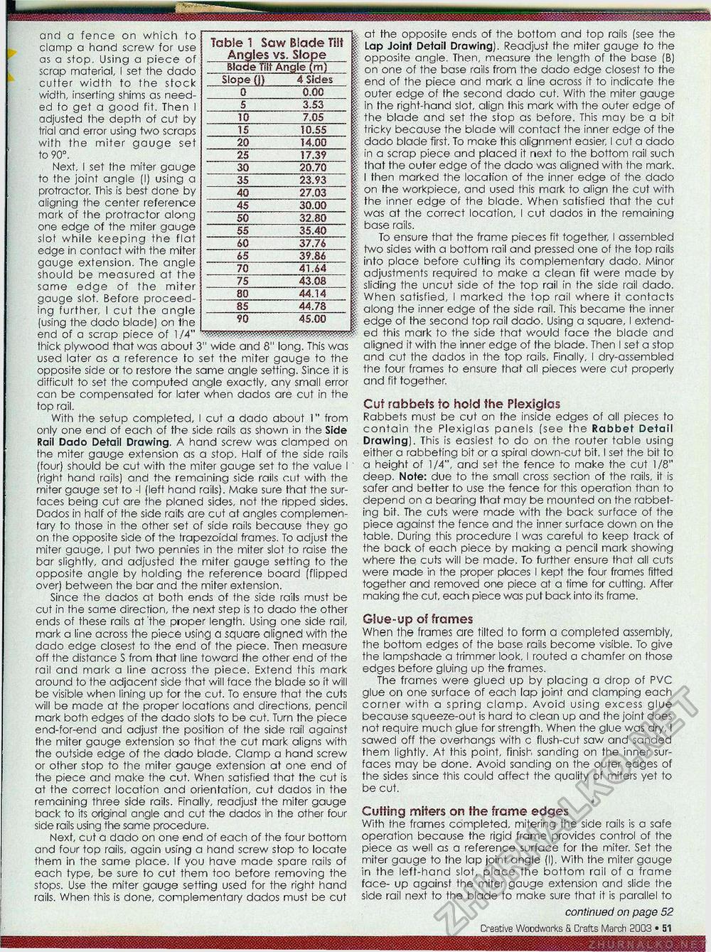
and a fence on which to clamp a hand screw for use as a stop. Using a piece of scrap material, I set the dado cutter width to the stock width, inserting shims as needed to get a good fit. Then I adjusted the depth of cut by trial and error using two scraps with the miter gauge set to 90°. Next, I set the miter gauge to the joint angle (I) using a protractor. This is best done by aligning the center reference mark of the protractor along one edge of the miter gauge slot while keeping the flat edge in contact with the miter gauge extension. The angle should be measured at the same edge of the miter gauge slot. Before proceeding further, I cut the angle (using the dado blade) on the end of a scrap piece of 1/4" thick plywood that was about 3" wide and 8" long. This was used later as a reference to set the miter gauge to the opposite side or to restore the same angle setting. Since it is difficult to set the computed angle exactly, any small error can be compensated for later when dados are cut in the top rail. With the setup completed, I cut a dado about 1" from only one end of each of the side rails as shown in the Side Rail Dado Detail Drawing. A hand screw was clamped on fhe miter gauge extension as a stop. Half of the side rails (four) should be cut with the miter gauge set to the value I (right hand rails) and the remaining side rails cut with the miter gauge set to -I (left hand rails). Make sure that the surfaces being cut are the planed sides, not the ripped sides. Dados in half of fhe side raits are cut at angles complementary to those in the other set of side rails because they go on the opposite side of the trapezoidal frames. To adjust the miter gauge, I put two pennies in the miter slot to raise the bar slightly, and adjusted the miter gauge setting to the opposite angle by holding the reference board (flipped over) between the bar and the miter extension. Since the dados at both ends of the side rails must be cut in the same direction, the next step is to dado the other ends of these rails at 'the proper length. Using one side rail, mark a line across the piece using a square aligned with the dado edge closest to the end of the piece. Then measure off the distance S from that line toward the other end of the rail and mark a line across the piece. Extend this mark around to the adjacent side that will face the blade so it will be visible when lining up for the cut. To ensure that the cuts will be made at the proper locations and directions, pencil mark both edges of the dado slots to be cut. Turn the piece end-for-end and adjust the position of the side rail against the miter gauge extension so that the cut mark aligns with the outside edge of the dado blade. Clamp a hand screw or other stop to the miter gauge extension at one end of the piece and make the cut. When satisfied that the cut is at the correct location and orientation, cut dados in the remaining three side rails. Finally, readjust the miter gauge back to its original angle and cut the dados in the other four side rails using the same procedure. Next, cut a dado on one end of each of the four bottom and four top rails, again using a hand screw stop to locate them in the same place. If you have made spare rails of each type, be sure to cut them too before removing the stops. Use the miter gauge setting used for the right hand rails. When this is done, complementary dados must be cut at the opposite ends of the bottom and top rails (see the Lap Joint Detail Drawing). Readjust fhe miter gauge to the opposite angle. Then, measure the length of the base (B) on one of the base rails from the dado edge closest to the end of the piece and mark a line across it to indicate fhe outer edge of fhe second dado cut. With the miter gauge in the right-hand slot, align this mark with the outer edge of the blade and set the stop as before. This may be a bit tricky because the blade will contact the inner edge of the dado blade first. To make this alignment easier, I cut a dado in a scrap piece and placed it next to the bottom rail such that the outer edge of the dado was aligned with the mark. I then marked the location of the inner edge of the dado on the workpiece, and used this mark to align the cut with the inner edge of the blade. When satisfied that the cut was at the correct location, I cut dados in the remaining base rails. To ensure that the frame pieces fit together, I assembled two sides with a bottom rail and pressed one of the top rails into place before cutting its complementary dado. Minor adjustments required to make a clean fit were made by sliding the uncut side of the top rail in the side rail dado. When satisfied, I marked the top rail where it contacts along the inner edge of the side rail. This became the inner edge of fhe second top rail dado. Using a square, I extended this mark to the side that would face the blade and aligned it with the inner edge of the blade. Then I set a stop and cut the dados in the top rails. Finally, I dry-assembled the four frames to ensure that all pieces were cut properly and fit together. Cut rabbets to hold the Plexiglas Rabbets must be cut on fhe inside edges of all pieces to contain the Plexiglas panels (see the Rabbet Detail Drawing). This is easiest to do on the router table using either a rabbeting bit or a spiral down-cut bit. I set the bit to a height of 1/4", and set the fence to make the cut 1/8" deep. Note: due to the small cross section of the rails, it is safer and better to use the fence for this operation than to depend on a bearing that may be mounted on the rabbeting bit. The cuts were made with the back surface of the piece against the fence and the inner surface down on the table. During this procedure I was careful to keep track of the back of each piece by making a pencil mark showing where the cuts will be made. To further ensure that all cuts were made in the proper places I kept the four frames fitted together and removed one piece at a time for cuffing. After making the cut, each piece was put back into its frame. Giue-up of frames When the frames are tilted to form a completed assembly, the bottom edges of the base rails become visible. To give the lampshade a trimmer look, I routed a chamfer on those edges before gluing up the frames. The frames were glued up by placing a drop of PVC glue on one surface of each lap joint and clamping each corner with a spring clamp. Avoid using excess glue because squeeze-out is hard to clean up and the joint does not require much glue for strength. When the glue was dry, I sawed off the overhangs with c flush-cut saw and sanded them lightly. At this point, finish sanding on the inner surfaces may be done. Avoid sanding on the outer edges of the sides since this could affect the quality of miters yet to be cut. » Cutting miters on the frame edges With the frames completed, mitering the side rails is a safe operation because the rigid frame provides control of the piece as well as a reference surface for fhe miter. Set the miter gauge to fhe lap joint angle (I). With the miter gauge in the left-hand slot, place the bottom rail of a frame face- up against the miter gauge extension and slide the side rail next to the blade to make sure that it is parallel to continued on page 52 12 • Creative Woodworks & Crafts March 2003 Base
90 45.00 90 45.00 |
||||||||||||||||||||||||||||||||||||||||||||


