Popular Woodworking 2002-10 № 130, страница 24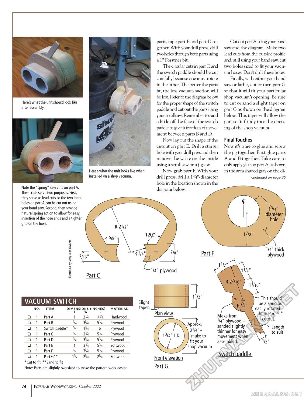
Here's what the unit looks like when installed on a shop vacuum. Note the "spring" saw cuts on part A. These cuts serve two purposes. First, they serve as lead cuts so the two inner holes on part A can be cut out using your band saw. Second, they provide natural spring action to allow for easy insertion of the hose ends and a tighter grip on the hose. parts, tape part B and part D together. With your drill press, drill two holes through both parts using a 1" Forstner bit. The circular cuts in part C and the switch paddle should be cut carefully because one must rotate in the other. The better the parts fit, the less vacuum suction will be lost. Refer to the diagram below for the proper shape of the switch paddle and cut out the parts using your scrollsaw. Remember to sand a little off the face of the switch paddle to give it freedom of movement between parts B and D. Now lay out the shape of the cutout on part E. Drill a starter hole with your drill press and then remove the waste on the inside using a scrollsaw or a jigsaw. Now grab part F. With your drill press, drill a 13/4" -diameter hole in the location shown in the diagram below. Cut out part A using your band saw and the diagram. Make two lead cuts from the outside profile and, still using your band saw, cut two holes sized to fit your vacuum hoses. Don't drill these holes. Finally, with either your band saw or lathe, cut or turn part G so that it will fit your particular shop vacuum's opening. Be sure to cut or sand a slight taper on part G as shown on the diagram below. This taper will allow the part to fit firmly into the opening of the shop vacuum. Final Touches Now it's time to glue and screw the jig together. First glue parts A and B together. Take care to only apply glue on part A as shown in the area shaded gray on the di-continued on page 26 VACUUM SWITCH
*Cut to fit; **Sand to fit Note: Parts are slightly oversized to make the pattern work easier This should be a snug but easily rotated fit in Part"C" cutout. Length to suit *Cut to fit; **Sand to fit Note: Parts are slightly oversized to make the pattern work easier Front elevation Part G Switch paddle 24 Popular Woodworking October 2002 |
||||||||||||||||||||||||||||||||||||||||||||||||||||||


