Popular Woodworking 2005-10 № 150, страница 88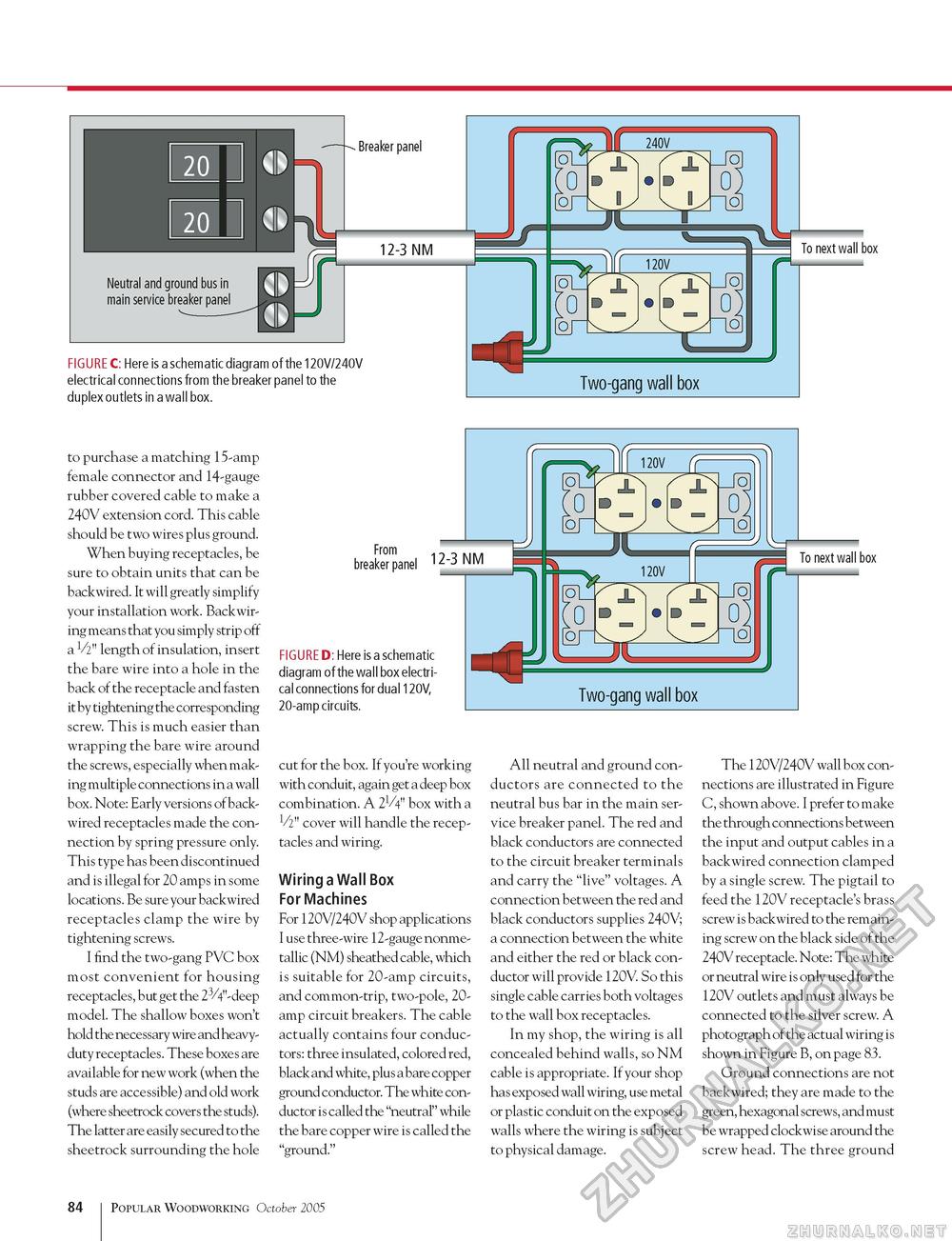
Breaker panel 12-3 NM FIGURE C: Here is a schematic diagram of the 120V/240V electrical connections from the breaker panel to the duplex outlets in a wall box. To next wall box to purchase a matching 15-amp female connector and 14-gauge rubber covered cable to make a 240V extension cord. This cable should be two wires plus ground. When buying receptacles, be sure to obtain units that can be backwired. It will greatly simplify your installation work. Backwir-ing means that you simply strip off a V2" length of insulation, insert the bare wire into a hole in the back of the receptacle and fasten it by tightening the corresponding screw. This is much easier than wrapping the bare wire around the screws, especially when making multiple connections in a wall box. Note: Early versions of back-wired receptacles made the connection by spring pressure only. This type has been discontinued and is illegal for 20 amps in some locations. Be sure your backwired receptacles clamp the wire by tightening screws. I find the two-gang PVC box most convenient for housing receptacles, but get the 23/4"-deep model. The shallow boxes won't hold the necessary wire and heavy-duty receptacles. These boxes are available for new work (when the studs are accessible) and old work (where sheetrock covers the studs). The latter are easily secured to the sheetrock surrounding the hole From .... breaker panel 12'3 NM FIGURE D: Here is a schematic diagram of the wall box electrical connections for dual 120V, 20-amp circuits. cut for the box. If you're working with conduit, again get a deep box combination. A 21/4" box with a V2" cover will handle the receptacles and wiring. Wiring a Wall Box For Machines For 120V/240V shop applications I use three-wire 12-gauge nonme-tallic (NM) sheathed cable, which is suitable for 20-amp circuits, and common-trip, two-pole, 20-amp circuit breakers. The cable actually contains four conductors: three insulated, colored red, black and white, plus a bare copper ground conductor. The white conductor is called the "neutral" while the bare copper wire is called the "ground." To next wall box All neutral and ground conductors are connected to the neutral bus bar in the main service breaker panel. The red and black conductors are connected to the circuit breaker terminals and carry the "live" voltages. A connection between the red and black conductors supplies 240V; a connection between the white and either the red or black conductor will provide 120V. So this single cable carries both voltages to the wall box receptacles. In my shop, the wiring is all concealed behind walls, so NM cable is appropriate. If your shop has exposed wall wiring, use metal or plastic conduit on the exposed walls where the wiring is subject to physical damage. The 120V/240V wall box connections are illustrated in Figure C, shown above. I prefer to make the through connections between the input and output cables in a backwired connection clamped by a single screw. The pigtail to feed the 120V receptacle's brass screw is backwired to the remaining screw on the black side of the 240V receptacle. Note: The white or neutral wire is only used for the 120V outlets and must always be connected to the silver screw. A photograph of the actual wiring is shown in Figure B, on page 83. Ground connections are not backwired; they are made to the green, hexagonal screws, and must be wrapped clockwise around the screw head. The three ground 84 Popular Woodworking October 2005 |


