41 - Fold-Down Drafting Table, страница 21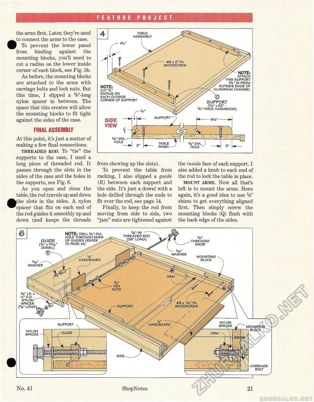
FEATURE PROJECT the arms first. Later, they're used ^^to connect the arms to the case. To prevent the lower panel from binding against the mounting blocks, you'll need to cut a radius on the lower inside corner of each block, see Fig. 5b. As before, the mounting blocks are attached to the arms with carriage bolts and lock nuts. But this time, I slipped a 3/8"-long nylon spacer in between. The space that this creates will allow the mounting blocks to fit tight against the sides of the case. FINAL ASSEMBLY At this point, it's just a matter of making a few final connections. threaded rod. To "tie" the supports to the case, I used a long piece of threaded rod. It passes through the slots in the sides of the case and the holes in the supports, see Fig. 6. As you open and close the table, the rod travels up and down •the slots in the sides. A nylon spacer that fits on each end of the rod guides it smoothly up and down (and keeps the threads from chewing up the slots). To prevent the table from racking, I also slipped a guide (R) between each support and the side. It's just a dowel with a hole drilled through the ends to fit over the rod, see page 14. Finally, to keep the rod from moving from side to side, two "jam" nuts are tightened against the inside face of each support. I also added a knob to each end of the rod to lock the table in place. mount arms. Now all that's left is to mount the arms. Here again, it's a good idea to use Vs" shims to get everything aligned first. Then simply screw the mounting blocks (Q) flush with the back edge of the sides. SIDE VIEW <E %"-DIA. H0LE—J 2" TABLE ASSEMBLY NOTE: ATTACH THIS SUPPORT W IN FROM OUTSIDE EDGE OF ALUMINUM CHANNEL SUPPORT (IV2" x 22" -3/4"-THICK HARDWOOD) NOTE: CUT %" RADIUS ON EACH OUTSIDE CORNER OF SUPPORT %"-DIA. HOLE SUPPORT r"7 MOUNTING BLOCK HARDBOARD ■ HEX NUTS #& x W Fh WOODSCREW SUPPORT / i/4" -- HARDBOARD GUIDE (%" X 1»/ie" DOWEL) CD- NOTE: DRILL %"-DIA. HOLE THROUGH ENDS OF GUIDES (REFER TO PAGE 14) 5/l 6" WASHER 3/e"-16-- THREADED ROD (36" LONG) THREADED KNOB - A&" WASHER NYLON SPACER "1 'I MOUNTING n BLOCK ARM SIDE CARRIAGE BOLT %" I.D. x 1/2" O.D. -NYLON SPACER (%" LONG) SUPPORT SUPPORT
No. 41 ShopNotes 21 |
||||||||||||||||||||


