65 - Our Best Bench Yet, страница 8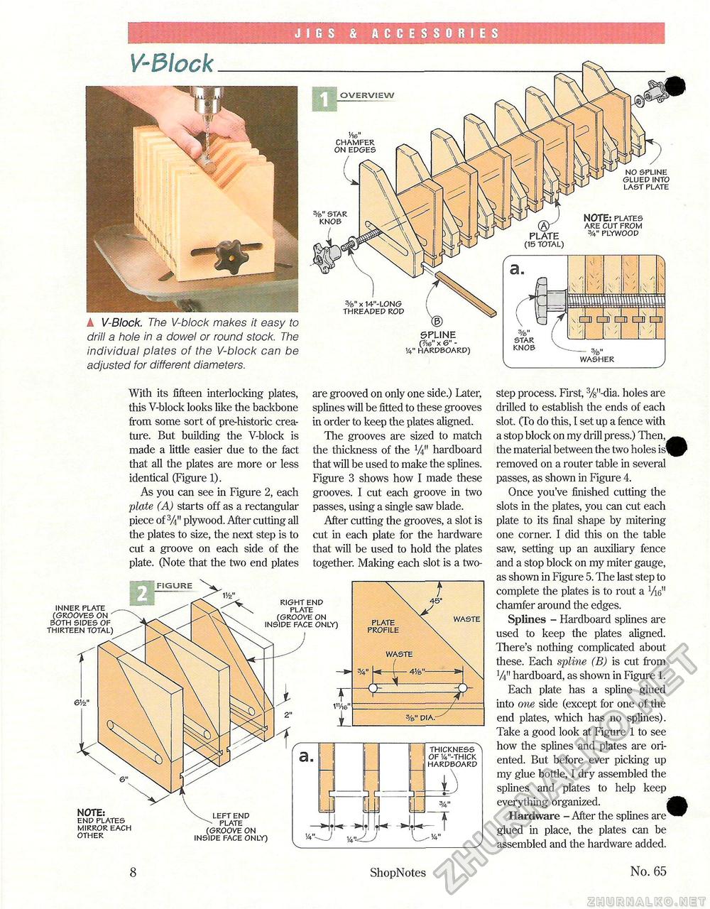
JIGS & ACCESSORIES V-Block step process. First, %"-dia. holes are drilled to establish the ends of each slot. (To do this, 1 set up a fence with a stop block on my drill press.) Then, the material between the two holes is' removed on a router table in several passes, as shown in Figure 4. Once you've finished cutting the slots in the plates, you can cut each plate to its final shape by mitering one corner. I did this on the table saw, setting up an auxiliary fence and a stop block on my miter gauge, as shown in Figure 5. The last step to complete the plates is to rout a Vie" chamfer around the edges. Splines - Hardboard splines are used to keep the plates aligned. There's nothing complicated about these. Each spline (B) is cut from V4" hardboard, as shown in Figure 1. Each plate has a spline glued into one side (except for one of the end plates, which has no splines). Take a good look at Figure 1 to see how the splines and plates are oriented. But before ever picking up my glue bottle, I dry assembled the splines and plates to help keep everything organized. | Hardware - After the splines are glued in place, the plates can be assembled and the hardware added. thickness 0f'/4"-thick hardboard A V-Block. The V-block makes it easy to drill a hole in a dowel or round stock. The individual plates of the V-block can be adjusted for different diameters. With its fifteen interlocking plates, this V-block looks like the backbone from some sort of pre-historic creature. But building the V-block is made a little easier due to the fact that all the plates are more or less identical (Figure 1). As you can see in Figure 2, each plate (A) starts off as a rectangular piece of 3A" plywood. After cutting all the plates to size, the next step is to cut a groove on each side of the plate. (Note that the two end plates are grooved on only one side.) Later, splines will be fitted to these grooves in order to keep the plates aligned. The grooves are sized to match the thickness of the V4" hardboard that will be used to make the splines. Figure 3 shows how I made these grooves. I cut each groove in two passes, using a single saw blade. After cutting the grooves, a slot is cut in each plate for the hardware that will be used to hold the plates together. Making each slot is a two- NOTE: end plates mirror each other left end plate (groove on inside face only) inner plate (grooves on both sides of thirteen total FIGURE right end plate (groove on inside face only) waste 3/4" U-(-4Ve" plate profile waste no spline glued into last plate %" star knob %" x 14"-L0NG threaded rod SPLINE (?16" X 6" - 1/4" hardboard) (15 total) NOTE: plates are cut from 3/4" plywood washer star knob 8 ShopNotes No. 65 |


