86, страница 30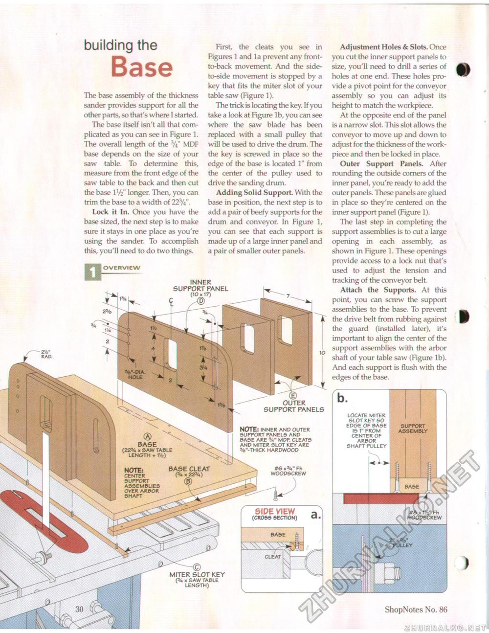
BASE (22% x SAW TABLE LENGTH + BASE CLEAT NOTE: CENTER SUPPORT ASSEMBLIES OVER ARBOR SHAFT SIDE VIEW (CROSS SECTION) « . building the The base assembly of the thickness sander provides support for all the other parts, so that's where I started. The base itself isn't all that complicated as you can see in Figure 1. The overall length of the MDF base depends on the size of your saw table. To determine this, measure from the front edge of the saw table to the back and then cut the base IV2" longer. Then, you can trim the base to a width of 223/4". Lock it In. Once you have the base sized, the next step is to make sure it stays in one place as you're using the sander. To accomplish this, you'll need to do two things. First, the cleats you see in Figures 1 and la prevent any front-to-back movement. And the side-to-side movement is stopped by a key that fits the miter slot of your table saw (Figure 1). The trick is locating the key. If you take a look at Figure lb, you can see where the saw blade has been replaced with a small pulley that will be used to drive the drum. The the key is screwed in place so the edge of the base is kxrated 1" from the center of the pulley used to drive the sanding drum. Adding Solid Support. With the base in position, the next step is to add a pair of beefy supports for the drum and conveyor. In Figure 1, you can see that each support is made up of a large inner panel and a pair of smaller outer panels. OVERVIEW INNER SUPPORT PANEL (10x17) V-WA. ' HOLE _ W OUTER SUPPORT PANELS NOTE: INNER AND OUTER SUPPORT PANELS AND BASE ARE MDF. CLEATS AND MITER SLOT KEY ARE V-THICK HARDWOOD Adjustment Holes & Slots. Once you cut the inner support panels to size, you'll need to drill a series of holes at one end. These holes provide a pivot point for the conveyor assembly so you can adjust its height to match the workpiece. At the opposite end of the panel is a narrow slot. This slot allows the conveyor to move up and down to adjust for the thickness of the work-piece and then be locked in place. Outer Support Panels. After rounding the outside corners of the inner panel, you're ready to add the outer panels. These panels are glued in place so they're centered on the inner support panel (Figure 1). The last step in completing the support assemblies is to cut a large opening in each assembly, as shown in Figure 1. These openings provide access to a lock nut that's used to adjust the tension and tracking of the conveyor belt. Attach the Supports. At this point, you can screw the support assemblies to the base. To prevent the drive belt from rubbing against the guard (installed later), it's important to align the center of the support assemblies with the arbor shaft of your table saw (Figure lb). And each support is flush with the edges of the base. MITER SLOT KEY x SAW TABLE LENGTH) 2V RAD. #6xV Fh WOODSCREW 30 ShopNotes No. 86 |


