86, страница 33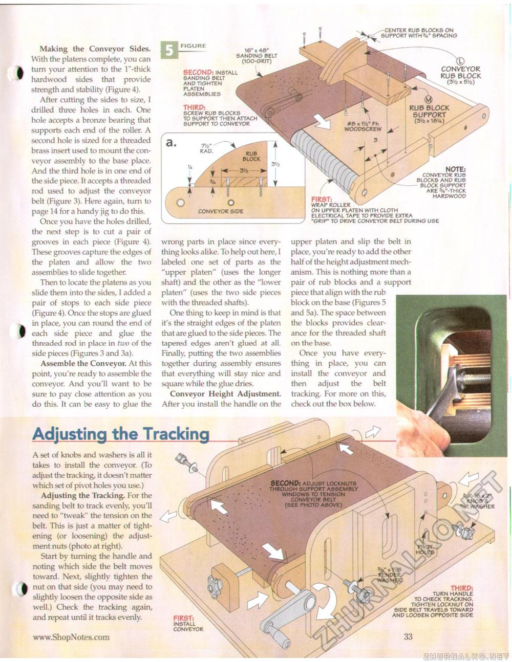
SECOND: adjust locknuts through support assembly windows to tension conveyor belt (see photo above) PIVOT HOLES x life" FENDER WASHER Making the Conveyor Sides. With the platens complete, you can turn your attention to the 1 "-thick hardwood sides that provide strength and stability (Figure 4). After cutting the sides to size, I drilled three holes in each. One hole accepts a bronze bearing that supports each end of the roller. A second hole is sized for a threaded brass insert used to mount the conveyor assembly to the base place. And the third hole is in one end of the side piece. It accepts a threaded rod used to adjust the conveyor belt (Figure 3). Here again, turn to page 14 for a handy jig to do this. Once you have the holes drilled, the next step is to cut a pair of grooves in each piece (Figure 4). These grooves capture the edges of the platen and allow the two assemblies to slide together. Then to locate the platens as you slide them into the sides, I added a pair of stops to each side piece (Figure 4). Once the stops are glued in place, you can round the end of each side piece and glue the threaded rod in place in two of the side pieces (Figures 3 and 3a). Assemble the Conveyor. At this point, you're ready to assemble the conveyor. And you'll want to be sure to pay close attention as you do this. It can be easy to glue the Adjusting the TrackingA set of knobs and washers is all it takes to install the conveyor. (To adjust the tracking, it doesn't matter which set of pivot holes you use.) Adjusting the Tracking. For the sanding belt to track evenly, you'll need to "tweak" the tension on the belt. This is just a matter of tightening (or loosening) the adjustment nuts (photo at right). Start by turning the handle and noting which side the belt moves toward. Next, slightly tighten the nut on that side (you may need to slightly loosen the opposite side as well.) Check the tracking again, and repeat until it tracks evenly. FIRST: INSTALL CONVEYOR *e"-16 x 2" KNOB & WASHER THIRD: TURN HANDLE TO CHECK TRACKING. TIGHTEN LOCKNUT ON SIDE BELT TRAVELS TOWARD AND LOOSEN OPPOSITE SIDE wrong parts in place since everything looks alike. To help out here, I labeled one set of parts as the "upper platen" (uses the longer shaft) and the other as the "lower platen" (uses the two side pieces with the threaded shafts). One thing to keep in mind is that it's the straight edges of the platen that are glued to the side pieces. The tapered edges aren't glued at all. Finally, putting the two assemblies together during assembly ensures that everything will stay nice and square while the glue dries. Conveyor Height Adjustment. After you install the handle on the 16" x 43" SANDING BELT (100-GRIT) SECOND: INSTALL SANDING BELT AND TIGHTEN PLATEN ASSEMBLIES THIRD: SCREW RUB BLOCKS TO SUPPORT THEN ATTACH SUPPORT TO CONVEYOR FIRST: WRAP ROLLER ON UPPER PLATEN WITH CLOTH ELECTRICAL TAPE TO PROVIDE EXTRA "GRIP" TO DRIVE CONVEYOR BELT DURING USE NOTE: fNVEYOR RUB BLOCKS AND RUB BLOCK SUPPORT ARE % "-THICK HARDWOOD upper platen and slip the belt in place, you're ready to add the other half of the height adjustment mechanism. This is nothing more than a pair of rub blocks and a support piece that align with the rub block on the base (Figures 5 and 5a). The space between the blocks provides clearance for the threaded shaft on the base. Once you have everything in place, you can install the conveyor and then adjust the belt tracking. For more on this, check out the box below. T/2" RAD. O o CONVEYOR SIDE CENTER RUB BLOCKS ON SUPPORT WITH V SPACING CONVEYOR RUB BLOCK (3H- x 5%) |


