86, страница 34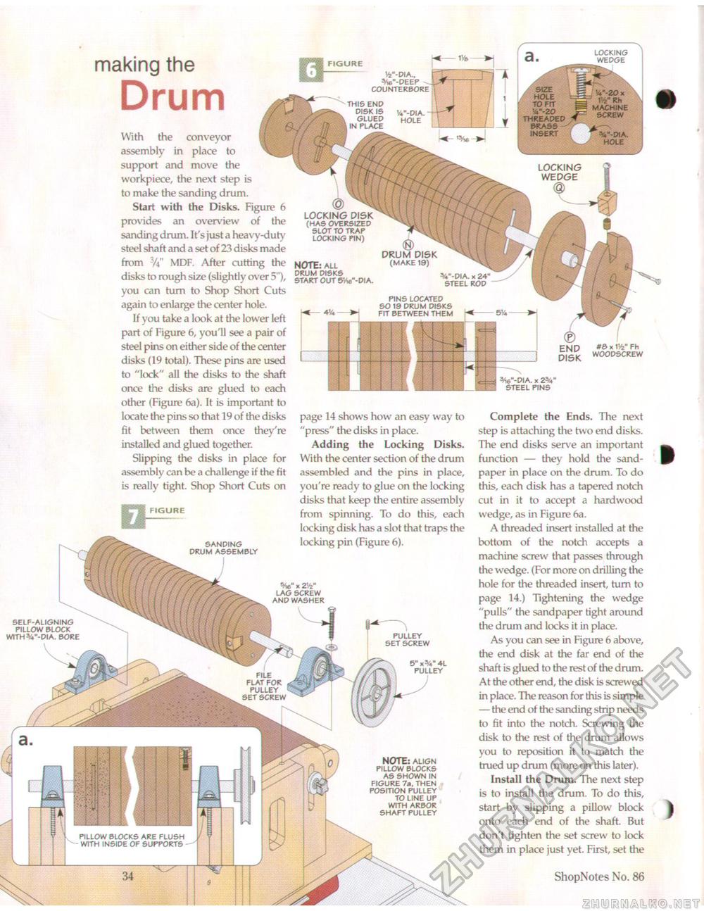
self-aligning pillow block withv4"-dia. bore making the DrumWith the conveyor assembly in place to support and move the workpiece, the next step is to make the sanding drum. Start with the Disks. Figure 6 provides an overview of the sanding drum. It's just a heavy-duty steel shaft and a set of 23 disks made from 3A" MDF. After cutting the disks to rough size (slightly over 5"), you can turn to Shop Short Cuts again to enlarge the center hole. If you take a look at the lower left part of Figure 6, you'll see a pair of steel pins on either side of the center disks (19 total). These pins are used to "lock" all the disks to the shaft once the disks are glued to each other (Figure 6a). It is important to locate the pins so that 19 of the disks fit between them once they're installed and glued together. Slipping the disks in place for assembly can be a challenge if the fit is really tight. Shop Short Cuts on ® LOCKING (has oversized slot to trap locking pin) NOTE: all drum disks start out 5vie"-dia. <fi) DRUM DISK (make 19) V-DIA. x 24" steel ROD pins located so 19 drum disks fit between them x W fh woodscrew page 14 shows how an easy way to "press" the disks in place. Adding the Locking Disks. With the center section of the drum assembled and the pins in place, you're ready to glue on the locking disks that keep the entire assembly from spinning. To do this, each locking disk has a slot that traps the locking pin (Figure 6). pulley set screw *6"-dia. x steel pins Complete the Ends. The next step is attaching the two end disks. The end disks serve an important function — they hold the sandpaper in place on the drum. To do this, each disk has a tapered notch cut in it to accept a hardwood wedge, as in Figure 6a. A threaded insert installed at the bottom of the notch accepts a machine screw that passes through the wedge. (For more on drilling the hole for the threaded insert, turn to page 14.) Tightening the wedge "pulls" the sandpaper tight around the drum and locks it in place. As you can see in Figure 6 above, the end disk at the far end of the shaft is glued to the rest of the drum. At the other end, the disk is screwed in place. The reason for this is simple — the end of the sanding strip needs to fit into the notch. Screwing the disk to the rest of the drum allows you to reposition it to match the trued up drum (more on this later). Install the Drum. The next step is to install the drum. To do this, start by slipping a pillow block onto each end of the shaft. But don't tighten the set screw to lock them in place just yet. First, set the 34 ShopNotes No. 86 |


