Woodworker's Journal 1980-4-5, страница 20
chest is set on the stretchers. The final touches can now be done. The trough ends, parts K, are ripped at a 45 degree angle and cut to size. Blind nailing will hold them to the bench ends. The bench screw handle comprises two pieces held together with a 5/«-inch mortise and tenon. This can be turned from a leftover scrap of 8/4 maple. Don't forget to round off the outside edges of the tail vise and front vise with a 3/»-inch router bit. At this point it's worthwhile to note that the top (F) is not glued to the base, thereby making it easier to disassemble and move. Part F simply fits on four dowels, two in each cleat (C), and is secured with one Vi" x 5" lag screw at the center of each part C. A belt sander and cabinet scraper will smooth the bench top. I would apply several coats of linseed oil. After this dries, apply several coats of tung oil and a coat of wax. A yearly coat of tung oil on the top of the bench will assure a smooth working surface. Editor's Note: Several workbench parts are specified as V* " thick. This is purchased as 1" nominal (4/4) stock that may actually measure between V* " and 13/16" thickness. If the 1" nominal stock you purchase measures more than Vt", it will be necessary to revise all affected dimensions accordingly. The other alternative is to plane the stock down to V*" thickness.
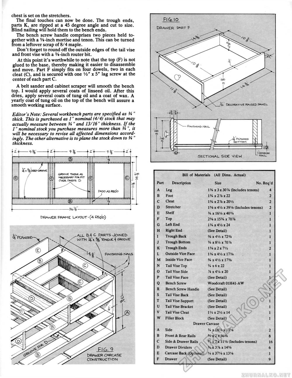
DRAWER FRAME LAYOUT-(4 RE<?d) DRAWER FRAME LAYOUT-(4 RE<?d)
fig. 9 Drawer carcase construction c parts joined WITH "I5NGUE 4 GROOVE: FlNISHlNS NAILS A |
||||||||||||||||||||||||||||||||||||||||||||||||||||||||||||||||||||||||||||||||||||||||||||||||||||||||||||||||||||||||||||||||||||||||||||||||||


