Woodworker's Journal 1983-7-1, страница 30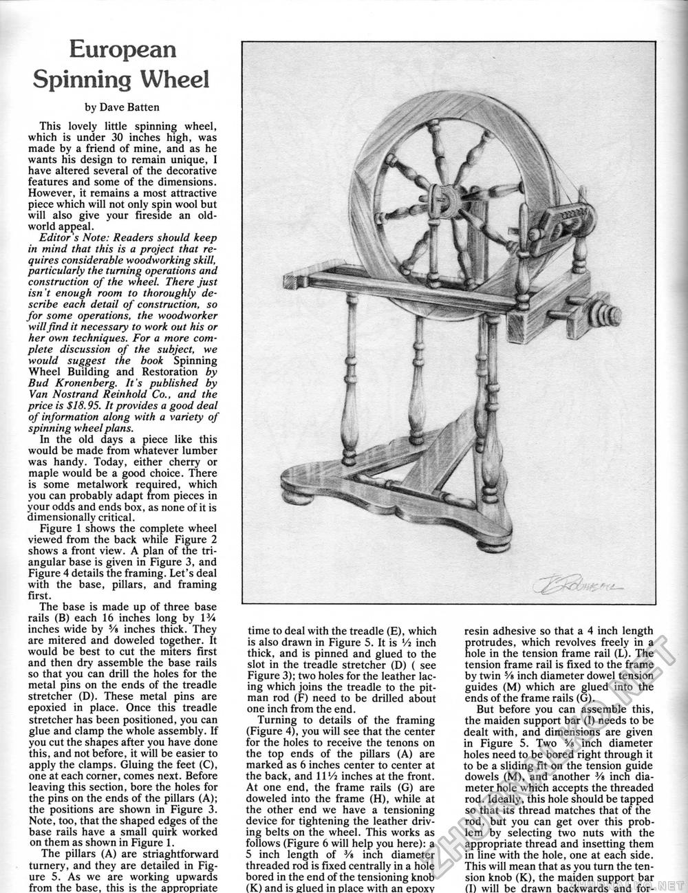
European Spinning Wheel by Dave Batten This lovely little spinning wheel, which is under 30 inches high, was made by a friend of mine, and as he wants his design to remain unique, I have altered several of the decorative features and some of the dimensions. However, it remains a most attractive piece which will not only spin wool but will also give your fireside an old-world appeal. Editor s Note: Readers should keep in mind that this is a project that requires considerable woodworking skill, particularly the turning operations and construction of the wheel. There just isn't enough room to thoroughly describe each detail of construction, so for some operations, the woodworker will find it necessary to work out his or her own techniques. For a more complete discussion of the subject, we would suggest the book Spinning Wheel Building and Restoration by Bud Kronenberg. It's published by Van Nostrand Reinhold Co., and the price is SI8.95. It provides a good deal of information along with a variety of spinning wheel plans. In the old days a piece like this would be made from whatever lumber was handy. Today, either cherry or maple would be a good choice. There is some metalwork required, which you can probably adapt from pieces in your odds and ends box, as none of it is dimensionally critical. Figure 1 shows the complete wheel viewed from the back while Figure 2 shows a front view. A plan of the triangular base is given in Figure 3, and Figure 4 details the framing. Let's deal with the base, pillars, and framing first. The base is made up of three base rails (B) each 16 inches long by W* inches wide by 5/« inches thick. They are mitered and doweled together. It would be best to cut the miters first and then dry assemble the base rails so that you can drill the holes for the metal pins on the ends of the treadle stretcher (D). These metal pins are epoxied in place. Once this treadle stretcher has been positioned, you can glue and clamp the whole assembly. If you cut the shapes after you have done this, and not before, it will be easier to apply the clamps. Gluing the feet (C), one at each corner, comes next. Before leaving this section, bore the holes for the pins on the ends of the pillars (A); the positions are shown in Figure 3. Note, too, that the shaped edges of the base rails have a small quirk worked on them as shown in Figure 1. The pillars (A) are striaghtforward turnery, and they are detailed in Figure 5. As we are working upwards from the base, this is the appropriate time to deal with the treadle (E), which is also drawn in Figure 5. It is Vi inch thick, and is pinned and glued to the slot in the treadle stretcher (D) ( see Figure 3); two holes for the leather lacing which joins the treadle to the pitman rod (F) need to be drilled about one inch from the end. Turning to details of the framing (Figure 4), you will see that the center for the holes to receive the tenons on the top ends of the pillars (A) are marked as 6 inches center to center at the back, and 11 Va inches at the front. At one end, the frame rails (G) are doweled into the frame (H), while at the other end we have a tensioning device for tightening the leather driving belts on the wheel. This works as follows (Figure 6 will help you here): a 5 inch length of Vt inch diameter threaded rod is fixed centrally in a hole bored in the end of the tensioning knob (K) and is glued in place with an epoxv resin adhesive so that a 4 inch length Erotrudes, which revolves freely in a ole in the tension frame rail (L). The tension frame rail is fixed to the frame by twin 5/e inch diameter dowel tension guides (M) which are glued into the ends of the frame rails (G). But before you can assemble this, the maiden support bar (I) needs to be dealt with, and dimensions are given in Figure 5. Two Ys inch diameter holes need to be bored right through it to be a sliding fit on the tension guide dowels (M), and another V» inch diameter hole which accepts the threaded rod. Ideally, this hole should be tapped so that its thread matches that of the rod, but you can get over this problem by selecting two nuts with the appropriate thread and insetting them in line with the hole, one at each side. This will mean that as you turn the tension knob (K), the maiden support bar (I) will be drawn backwards and for- |


