Woodworker's Journal 1983-7-1, страница 33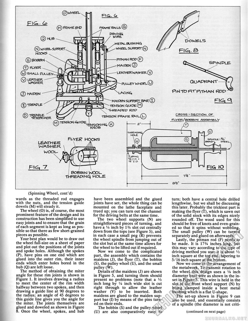
Fie,- 6? HUB ®WHEEl_S0eR3?T HOCMS © FL-YSR © SMALL- PULLE* (y) L6MHER. w WASHER. FIG,. G> FRAME RAtLS^ PRlVlskS, / WIRE ^ .METAL BUSH INla "L^^ WHEEL 5Uf?mr(N) -PITMAM R0P(?) -MAIDEN © - LEATHER WASHER (V) -PULLEV WHORV© ^LAONG, MAIPEN SJPFCKTBAK (i) TEMSCN AUIPE© THfcEAPeP ROC? TBM5I0NJ FRAME KAU_(L) PUYEf? HOOKS LEATHER \ Jk WASHER \ X-dm* woou BOBBIN WOOU THKEAPINLq HOUE QU APF?ANT PlNlTO Ftr PiTMAN ROP CROSS-SE.OTIOM OF FLVeR/BOeBlH ASSEMe.LV (t) mwwvmwwwwwwww InJ FIG IO (Spinning Wheel, cont'd) wards as the threaded rod engages with the nuts, and the tension guide dowels (M) will steady it. The wheel (0) is, of course, the most prominent feature of the design and its construction has been simplified to use easy joints and to ensure that the grain of each segment is kept as long as possible so that there as few short-grained pieces as possible. Your best plan would be to draw out the wheel full-size on a sheet of paper and plot out the positions of the joints and spoke holes. Although the spokes (P), have pins on one end which are glued into the outer rim, their inner ends which enter holes bored in the hub (Q) are left loose. The method of obtaining the miter angle for these rim joints is shown in Figure 1. It involves drawing a radius to meet the center of the rim width halfway between two spokes, and then drawing a guide line at 90 degrees to the radius; an angle of 45 degrees to this guide line gives you the angle for the miter. The joints themselves are glued and doweled as shown in Figure 8. Once the wheel, spokes, and hub have been assembled and the glued joints have set, the whole thing can be mounted on the lathe faceplate and trued up; you can turn out the channel for the driving belts at the same time. The two wheel supports (N) are straightforward pieces of turning, and have a V* inch by 1V* slot cut centrally down from the tops (see Figure 5), and in each case a small peg (R) prevents the wheel spindle from jumping out of the slot but at the same time allows for the wheel to be lifted out if required. Now we come to the complicated part, the assembly which contains the maidens (J), the flyer (T), the bobbin (S), the pulley whorl (U), and the small pulley (W). Details of the maidens (J) are shown in Figure 5, and turning them should present no problems (note that a Vi inch long by V* inch wide slot is cut right through to allow the leather washer (V) to be inserted. Both maidens are glued to the maiden support bar (I) by means of the pins turned on their ends. The bobbin (S) and the pulley whorl (U) are also comparatively easy to turn; both have a central hole drilled lengthwise, but we shall be discussing this later. Probably the trickiest part is making the flyer (T), which is sawn out of the solid stock with its edges nicely rounded off. The wood used for this should be free of knots and even-grained so that it spins without wobbling. The small pulley (W) can be turned separately and glued on afterwards. Lastly, the pitman rod (F) needs to be made. It is 173/« inches long, but this may vary according to the type of driving method you use; it is about Vi inch square at the top end, tapering to 5/16 inch square at the bottom. Now we come to the arrangement of the metal work. To transmit rotation to the wheel this design uses a Vs inch diameter bent wire as shown in the inset in Figure 5. This wire is held in the slot of the front wheel support (N) by being clamped inside a bent metal bushing which is a flat U-shape. The set-up shown in Figure 9 can also be used, and essentially consists of a spindle (the diameter is not criti- (continued on next page) |


