Woodworker's Journal 1983-7-1, страница 34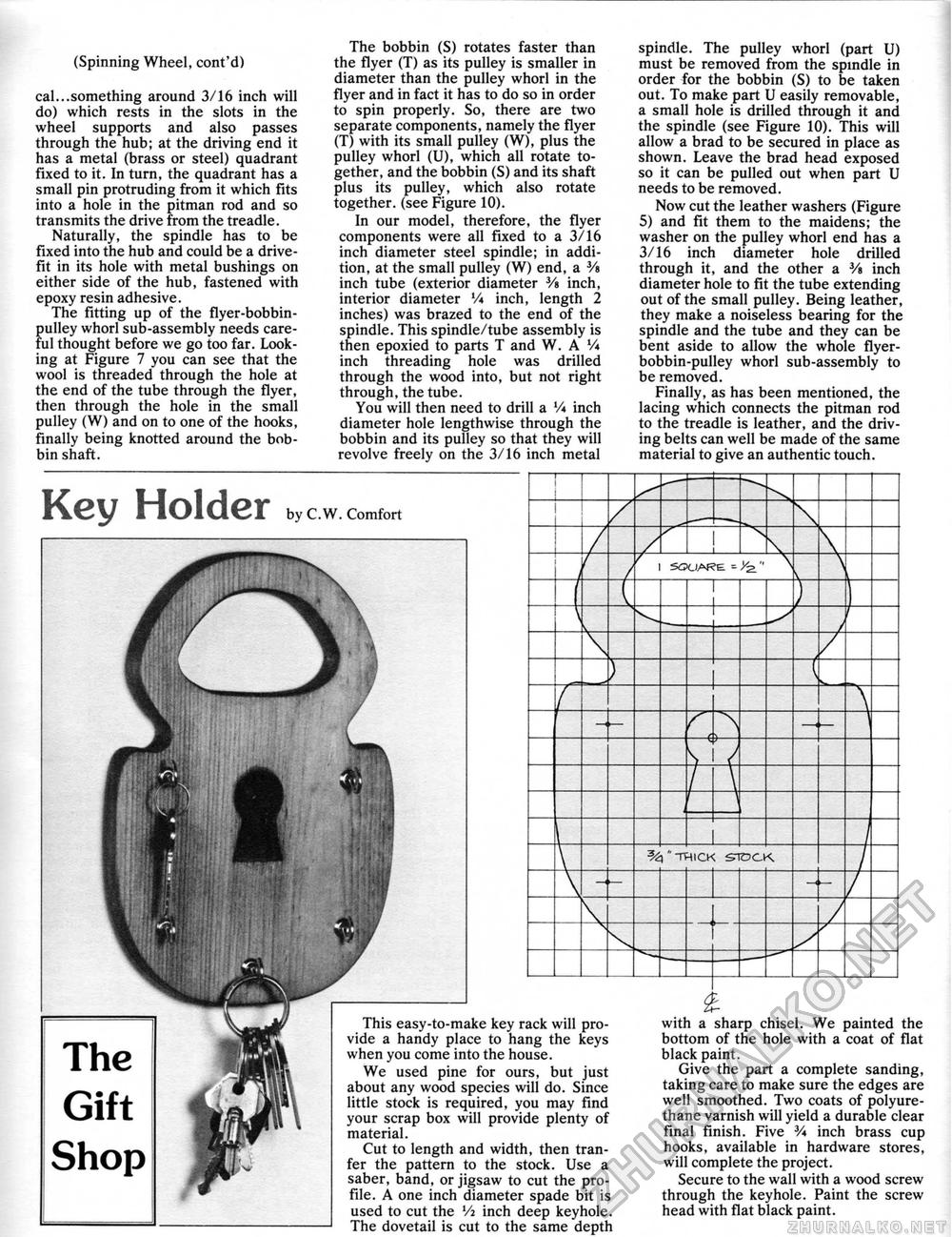
(Spinning Wheel, cont'd) cal...something around 3/16 inch will do) which rests in the slots in the wheel supports and also passes through the hub; at the driving end it has a metal (brass or steel) quadrant fixed to it. In turn, the quadrant has a small pin protruding from it which fits into a hole in the pitman rod and so transmits the drive from the treadle. Naturally, the spindle has to be fixed into the hub and could be a drive-fit in its hole with metal bushings on either side of the hub, fastened with epoxy resin adhesive. The fitting up of the flyer-bobbin-pulley whorl sub-assembly needs careful thought before we go too far. Looking at Figure 7 you can see that the wool is threaded through the hole at the end of the tube through the flyer, then through the hole in the small pulley (W) and on to one of the hooks, finally being knotted around the bobbin shaft. The bobbin (S) rotates faster than the flyer (T) as its pulley is smaller in diameter than the pulley whorl in the flyer and in fact it has to do so in order to spin properly. So, there are two separate components, namely the flyer (T) with its small pulley (W), plus the pulley whorl (U), which all rotate together, and the bobbin (S) and its shaft plus its pulley, which also rotate together, (see Figure 10). In our model, therefore, the flyer components were all fixed to a 3/16 inch diameter steel spindle; in addition, at the small pulley (W) end, a V» inch tube (exterior diameter 3/s inch, interior diameter Vi inch, length 2 inches) was brazed to the end of the spindle. This spindle/tube assembly is then epoxied to parts T and W. A Vi inch threading hole was drilled through the wood into, but not right through,the tube. You will then need to drill a Vi inch diameter hole lengthwise through the bobbin and its pulley so that they will revolve freely on the 3/16 inch metal spindle. The pulley whorl (part U) must be removed from the spindle in order for the bobbin (S) to be taken out. To make part U easily removable, a small hole is drilled through it and the spindle (see Figure 10). This will allow a brad to be secured in place as shown. Leave the brad head exposed so it can be pulled out when part U needs to be removed. Now cut the leather washers (Figure 5) and fit them to the maidens; the washer on the pulley whorl end has a 3/16 inch diameter hole drilled through it, and the other a V» inch diameter hole to fit the tube extending out of the small pulley. Being leather, they make a noiseless bearing for the spindle and the tube and they can be bent aside to allow the whole flyer-bobbin-pulley whorl sub-assembly to be removed. Finally, as has been mentioned, the lacing which connects the pitman rod to the treadle is leather, and the driving belts can well be made of the same material to give an authentic touch. Key Holder by C.W. Comfort This easy-to-make key rack will provide a handy place to hang the keys when you come into the house. We used pine for ours, but just about any wood species will do. Since little stock is required, you may find your scrap box will provide plenty of material. Cut to length and width, then tran-fer the pattern to the stock. Use a saber, band, or jigsaw to cut the profile. A one inch diameter spade bit is used to cut the Vi inch deep keyhole. The dovetail is cut to the same depth with a sharp chisel. We painted the bottom of the hole with a coat of flat black paint. Give the part a complete sanding, taking care to make sure the edges are well smoothed. Two coats of polyurethane varnish will yield a durable clear final finish. Five V* inch brass cup hooks, available in hardware stores, will complete the project. Secure to the wall with a wood screw through the keyhole. Paint the screw head with flat black paint. |


