Woodworker's Journal 1983-7-3, страница 32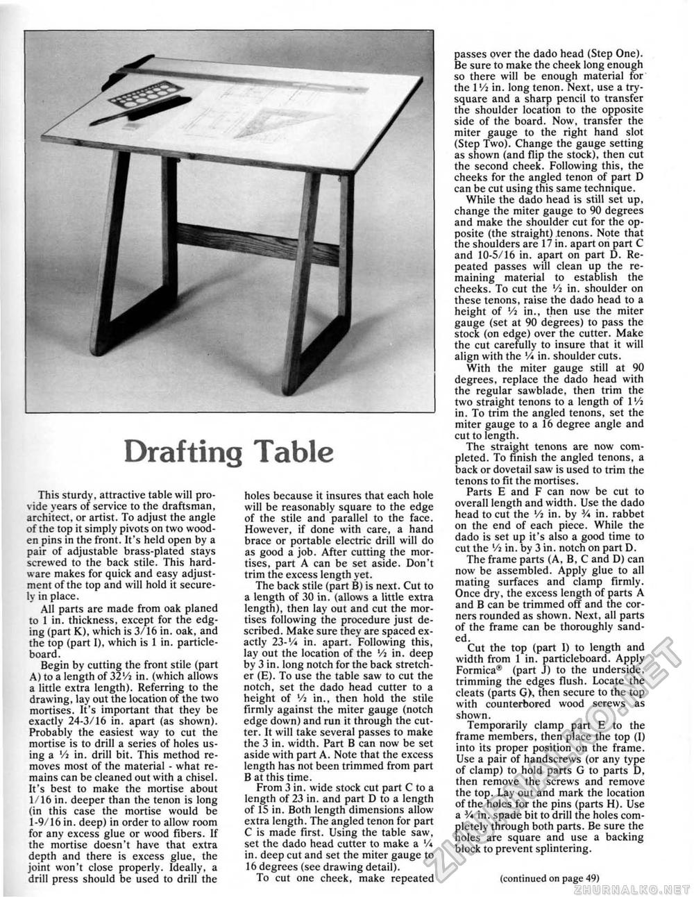
- Drafting TableThis sturdy, attractive table will provide years of service to the draftsman, architect, or artist. To adjust the angle of the top it simply pivots on two wooden pins in the front. It's held open by a pair of adjustable brass-plated stays screwed to the back stile. This hardware makes for quick and easy adjustment of the top and will hold it securely in place. All parts are made from oak planed 10 1 in. thickness, except for the edging (part K), which is 3/16 in. oak, and the top (part 1), which is 1 in. particle-board. Begin by cutting the front stile (part A) to a length of 32'/j in. (which allows a little extra length). Referring to the drawing, lay out the location of the two mortises. It's important that they be exactly 24-3/16 in. apart (as shown). Probably the easiest way to cut the mortise is to drill a series of holes using a Vi in. drill bit. This method removes most of the material - what remains can be cleaned out with a chisel. It's best to make the mortise about 1/16 in. deeper than the tenon is long (in this case the mortise would be I-9/16 in, deep) in order to allow room for any excess glue or wood fibers. If the mortise doesn't have that extra depth and there is excess glue, the joint won't close properly. Ideally, a drill press should be used to drill the holes because it insures that each hole will be reasonably square to the edge of the stile and parallel to the face. However, if done with care, a hand brace or portable electric drill will do as good a job. After cutting the mortises. part A can be set aside. Don't trim the excess length yet. The back stile (part B) is next. Cut to a length of 30 in, (allows a little extra length), then lay out and cut the mortises following the procedure just described. Make sure they are spaced exactly 23-V* in. apart. Following this, lay out the location of the Vi in. deep by 3 in, long notch for the back stretcher (E). To use the table saw to cut the notch, set the dado head cutter to a height of Vi in., then hold the stile firmly against the miter gauge (notch edge down) and run it through the cutter. It will take several passes to make the 3 in. width. Part B can now be set aside with part A. Note that the excess length has not been trimmed from part B at this time. From 3 in. wide stock cut part C to a length of 23 in. and part D to a length of 15 in. Both length dimensions allow extra length. The angled tenon for part C is made first. Using the table saw, set the dado head cutter to make a V* in. deep cut and set the miter gauge to 16 degrees (see drawing detail). To cut one cheek, make repeated passes over the dado head (Step One). Be sure to make the cheek long enough so there will be enough material for the 1 Vi in. long tenon. Next, use a try-square and a sharp pencil to transfer the shoulder location to the opposite side of the board. Now, transfer the miter gauge to the right hand slot (Step Two). Change the gauge setting as shown (and flip the stock), then cut the second cheek. Following this, the cheeks for the angled tenon of part D can be cut using this same technique. While the dado head is still set up, change the miter gauge to 90 degrees and make the shoulder cut for the opposite (the straight) tenons. Note that the shoulders are 17 in. apart on part C and 10-5/16 in. apart on part D. Repeated passes will clean up the remaining material to establish the cheeks. To cut the Vi in. shoulder on these tenons, raise the dado head to a height of '/j in., then use the miter gauge (set at 90 degrees) to pass the stock (on edge) over the cutter. Make the cut carefully to insure that it will align with the '/i in. shoulder cuts. With the miter gauge still at 90 degrees, replace the dado head with the regular sawblade, then trim the two straight tenons to a length of l'/i in. To trim the angled tenons, set the miter gauge to a 16 degree angle and cut to length. The straight tenons are now completed. To finish the angled tenons, a back or dovetail saw is used to trim the tenons to fit the mortises. Parts E and F can now be cut to overall length and width. Use the dado head to cut the Vt in. by V* in. rabbet on the end of each piece. While the dado is set up it's also a good time to cut the Vi in. by 3 in, notch on part D, The frame parts (A, B, C and D) can now be assembled. Apply glue to all mating surfaces and clamp firmly. Once dry, the excess length of parts A and B can be trimmed off and the corners rounded as shown. Next, all parts of the frame can be thoroughly sanded. Cut the top (part I) to length and width from i in. particleboard. Apply Formica® (part J) to the underside, trimming the edges flush. Locate the cleats (parts G>, then secure to the top with counterbored wood screws as shown. Temporarily clamp part E to the frame members, then place the top (I) into its proper position on the frame. Use a pair of handscrews (or any type of clamp) to hold parts G to parts* D, then remove the screws and remove the top. Lay out and mark the location of the holes for the pins (parts H), Use a V* in, spade bit to drill the holes completely through both parts. Be sure the holes are square and use a backing block to prevent splintering. (continued on page 49) |


