Woodworker's Journal 1984-8-2, страница 33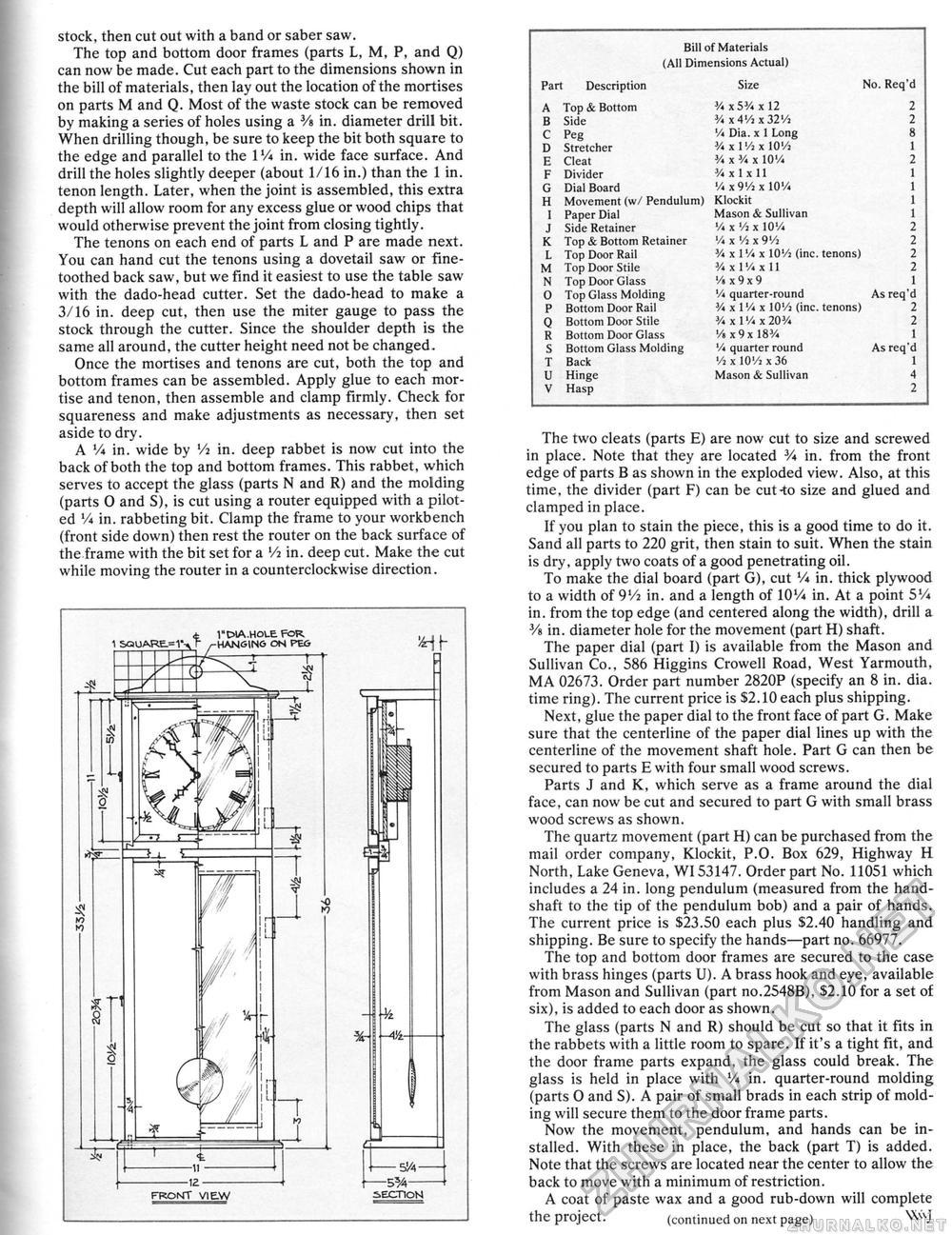
stock, then cut out with a band or saber saw. The top and bottom door frames (parts L, M, P, and Q) can now be made. Cut each part to the dimensions shown in the bill of materials, then lay out the location of the mortises on parts M and Q. Most of the waste stock can be removed by making a series of holes using a 3/s in. diameter drill bit. When drilling though, be sure to keep the bit both square to the edge and parallel to the IVi in. wide face surface. And drill the holes slightly deeper (about 1/16 in.) than the i in. tenon length. Later, when the joint is assembled, this extra depth will allow room for any excess glue or wood chips that would otherwise prevent the joint from closing tightly. The tenons on each end of parts L and P are made next. You can hand cut the tenons using a dovetail saw or fine-toothed back saw, but we find it easiest to use the table saw with the dado-head cutter. Set the dado-head to make a 3/16 in. deep cut, then use the miter gauge to pass the stock through the cutter. Since the shoulder depth is the same all around, the cutter height need not be changed. Once the mortises and tenons are cut, both the top and bottom frames can be assembled. Apply glue to each mortise and tenon, then assemble and clamp firmly. Check for squareness and make adjustments as necessary, then set aside to dry. A V* in. wide by Vi in. deep rabbet is now cut into the back of both the top and bottom frames. This rabbet, which serves to accept the glass (parts N and R) and the molding (parts 0 and S), is cut using a router equipped with a piloted V* in. rabbeting bit. Clamp the frame to your workbench (front side down) then rest the router on the back surface of the frame with the bit set for a Vi in. deep cut. Make the cut while moving the router in a counterclockwise direction. Bill of Materials (All Dimensions Actual) Bill of Materials (All Dimensions Actual)
The two cleats (parts E) are now cut to size and screwed in place. Note that they are located 3A in. from the front edge of parts B as shown in the exploded view. Also, at this time, the divider (part F) can be cut-to size and glued and clamped in place. If you plan to stain the piece, this is a good time to do it. Sand all parts to 220 grit, then stain to suit. When the stain is dry, apply two coats of a good penetrating oil. To make the dial board (part G), cut V« in. thick plywood to a width of 9Vi in. and a length of 10V* in. At a point 5V* in. from the top edge (and centered along the width), drill a 3/s in. diameter hole for the movement (part H) shaft. The paper dial (part I) is available from the Mason and Sullivan Co., 586 Higgins Crowell Road, West Yarmouth, MA 02673. Order part number 2820P (specify an 8 in. dia. time ring). The current price is $2.10 each plus shipping. Next, glue the paper dial to the front face of part G. Make sure that the centerline of the paper dial lines up with the centerline of the movement shaft hole. Part G can then be secured to parts E with four small wood screws. Parts J and K, which serve as a frame around the dial face, can now be cut and secured to part G with small brass wood screws as shown. The quartz movement (part H) can be purchased from the mail order company, Klockit, P.O. Box 629, Highway H North, Lake Geneva", WI53147. Order part No. 11051 which includes a 24 in. long pendulum (measured from the hand-shaft to the tip of the pendulum bob) and a pair of hands. The current price is $23.50 each plus $2.40 handling and shipping. Be sure to specify the hands—part no. 66977. The top and bottom door frames are secured to the case with brass hinges (parts U). A brass hook and eye, available from Mason and Sullivan (part no.2548B), $2.10 for a set of six), is added to each door as shown. The glass (parts N and R) should be cut so that it fits in the rabbets with a little room to spare. If it's a tight fit, and the door frame parts expand, the glass could break. The glass is held in place with V* in. quarter-round molding (parts O and S). A pair of small brads in each strip of molding will secure them to the door frame parts. Now the movement, pendulum, and hands can be installed. With these in place, the back (part T) is added. Note that the screws are located near the center to allow the back to move with a minimum of restriction. A coat of paste wax and a good rub-down will complete the project. (continued ott next page) |
||||||||||||||||||||||||||||||||||||||||||||||||||||||||||||||||||||||||||||||||||||||||||||


