Woodworker's Journal 1984-8-3, страница 29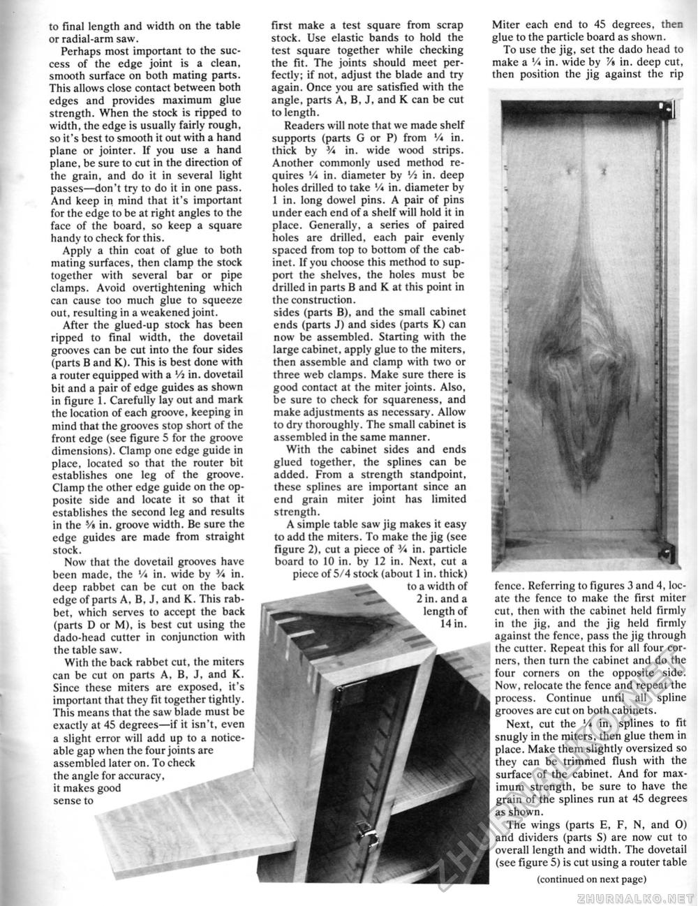
to final length and width on the table or radial-arm saw. Perhaps most important to the success of the edge joint is a clean, smooth surface on both mating parts. This allows close contact between both edges and provides maximum glue strength. When the stock is ripped to width, the edge is usually fairly rough, so it's best to smooth it out with a hand plane or jointer. If you use a hand plane, be sure to cut in the direction of the grain, and do it in several light passes—don't try to do it in one pass. And keep in mind that it's important for the edge to be at right angles to the face of the board, so keep a square handy to check for this. Apply a thin coat of glue to both mating surfaces, then clamp the stock together with several bar or pipe clamps. Avoid overtightening which can cause too much glue to squeeze out, resulting in a weakened joint. After the glued-up stock has been ripped to final width, the dovetail grooves can be cut into the four sides (parts B and K). This is best done with a router equipped with a 'A in. dovetail bit and a pair of edge guides as shown in figure 1. Carefully lay out and mark the location of each groove, keeping in mind that the grooves stop short of the front edge (see figure 5 for the groove dimensions). Clamp one edge guide in place, located so that the router bit establishes one leg of the groove. Clamp the other edge guide on the opposite side and locate it so that it establishes the second leg and results in the V$ in. groove width. Be sure the edge guides are made from straight stock. Now that the dovetail grooves have been made, the '/« in. wide by V* in. deep rabbet can be cut on the back edge of parts A, B, J, and K. This rabbet, which serves to accept the back (parts D or M), is best cut using the dado-head cutter in conjunction with the table saw. With the back rabbet cut, the miters can be cut on parts A, B, J, and K. Since these miters are exposed, it's important that they fit together tightly. This means that the saw blade must be exactly at 45 degrees—if it isn't, even a slight error will add up to a noticeable gap when the four joints are assembled later on. To check the angle for accuracy, it makes good sense to first make a test square from scrap stock. Use elastic bands to hold the test square together while checking the fit. The joints should meet perfectly; if not, adjust the blade and try again. Once you are satisfied with the angle, parts A, B, J, and K can be cut to length. Readers will note that we made shelf supports (parts G or P) from V♦ in. thick by V* in. wide wood strips. Another commonly used method requires V* in. diameter by Vi in. deep holes drilled to take '/* in. diameter by 1 in. long dowel pins. A pair of pins under each end of a shelf will hold it in place. Generally, a series of paired holes are drilled, each pair evenly spaced from top to bottom of the cabinet. If you choose this method to support the shelves, the holes must be drilled in parts B and K at this point in the construction. sides (parts B), and the small cabinet ends (parts J) and sides (parts K) can now be assembled. Starting with the large cabinet, apply glue to the miters, then assemble and clamp with two or three web clamps. Make sure there is good contact at the miter joints. Also, be sure to check for squareness, and make adjustments as necessary. Allow to dry thoroughly. The small cabinet is assembled in the same manner. With the cabinet sides and ends glued together, the splines can be added. From a strength standpoint, these splines are important since an end grain miter joint has limited strength. A simple table saw jig makes it easy to add the miters. To make the jig (see figure 2), cut a piece of V* in. particle board to 10 in. by 12 in. Next, cut a piece of 5/4 stock (about 1 in. thick) to a width of 2 in.and a length of 14 in. Miter each end to 45 degrees, then glue to the particle board as shown. To use the jig, set the dado head to make a '/* in. wide by V* in. deep cut, then position the jig against the rip fence. Referring to figures 3 and 4, locate the fence to make the first miter cut, then with the cabinet held firmly in the jig, and the jig held firmly against the fence, pass the jig through the cutter. Repeat this for all four corners, then turn the cabinet and do the four corners on the opposite side. Now, relocate the fence and repeat the process. Continue until all spline grooves are cut on both cabinets. Next, cut the V* in. splines to fit snugly in the miters, then glue them in place. Make them slightly oversized so they can be trimmed flush with the surface of the cabinet. And for maximum strength, be sure to have the grain of the splines run at 45 degrees as shown. The wings (parts E, F, N, and 0) and dividers (parts S) are now cut to overall length and width. The dovetail (see figure 5) is cut using a router table (continued on next page) |


