Woodworker's Journal 1984-8-6, страница 60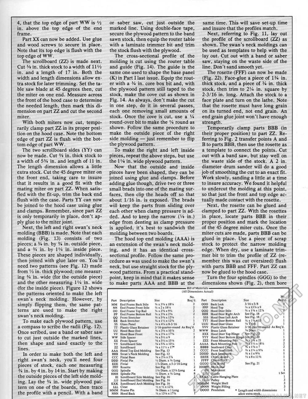
4, that the top edge of part WW is Vi in. above the top edge of the end frame. Part XX can now be added. Use glue and wood screws to secure in place. Note that its top edge is flush with the top edge of WW. The scrollboard (ZZ) is made next. Cut Ys in. thick stock to a width of IIVj in. and a length of 17 in. Both the width and length dimensions allow extra stock for later trimming. Set the table saw blade at 45 degrees then, cut the miter on one end. Measure across the front of the hood case to determine the needed length, then mark this dimension on part ZZ and cut the second miter. With both miters now cut, temporarily clamp part ZZ in its proper position on the hood case. Note the bottom edge of part ZZ is flush with the bottom edge of part WW. The two scrollboard sides (YY) can now be made. Cut 5/i in. thick stock to a width of 53A in. and length of 11 in. The length dimension allows a little extra stock. Cut the 45 degree miter on the front end, taking care to insure that it results in a good Fit with the mating miter on part ZZ. When satisfied with the fit-up, trim the back end flush with the case. Parts YY can now be joined to the hood case using glue and clamps. Remember, since part ZZ is only temporarily in place, don't apply glue to the miter joint. Next, the left and right swan's neck molding (BBB) is made. Note that each molding (Fig. 13) consists of two pieces; a 3A in, by V* in. outside piece, and a 3A in. by VA in. inside piece. These pieces are shaped individually, then joined with glue later on. You'll need two patterns (see Fig. 12) made from Vi in. thick plywood; one measuring 3A in. wide (for the outside piece) and the other measuring VA in. wide (for the inside piece), Figure 12 shows the patterns oriented to make the left swan's neck molding. However, by simply flipping them, the same patterns are used to make the right swan's neck molding. To make each plywood pattern, use a compass to scribe the radii (Fig. 12). Once scribed, use a band or saber saw to cut just outside the marked lines, then shape and sand exactly to the lines. In order to make both the left and right swan's neck, you'll need four pieces of stock, each one measuring 3A in. by 4 in. by 14 in. Start by making the outside pieces of the left side molding. Lay the 3A in. wide plywood pattern on one of the boards, then trace the profile with a pencil. With a band or saber saw, cut just outside the marked line. Using double-face tape, secure the plywood pattern to the band sawn stock, then equip the router table with a laminate trimmer bit and trim the stock flush with the plywood. The cross-sectional profile of the molding is cut using the router table and guide (Fig. 14). The guide is the same one used to shape the base panel (K) in Part I last issue. Equip the router with a V* in. core box bit and, with the plywood pattern still taped to the stock, make the cove cut as shown in Fig. 14. As always, don't make the cut in one step, do it in several passes, each one removing small amounts of stock. Once the cove is cut, use a V* round-over bit to make the V* round as shown. Follow the same procedure to make the outside piece of the right side molding — just remember to flip the plywood pattern. To make the right and left inside pieces, repeat the above steps, but use the VA in. wide plywood pattern. Now that the outside and inside pieces have been shaped, they can be joined using glue and clamps. Before adding glue though, drive two or three small brads into one of the mating surfaces, then clip the heads off so that about 1/16 in. is exposed. The brads will keep the parts from sliding over each other when clamp pressure is added. And to keep the narrow (V* in.) edge from denting as clamp pressure is applied, it's best to sandwich the molding between two boards. The hood top end molding (AAA) is an extension of the swan's neck molding, and it has an identical cross-sectional profile. Follow the same procedure as was used to make the swan's neck, but use straight stock for the plywood patterns. From a practical standpoint, keep in mind that it makes sense to make parts AAA and BBB at the same time. This will save set-up time and insure that the profiles match. Next, referring to Fig. 11, lay out the profile of the scrollboard (ZZ) as shown. The swan's neck moldings can be used as templates to help with the lay out. Cut out with a band or saber saw, staying on the waste side of the line. Don't sand smooth yet. The rosette (FFF) can now be made (Fig. 22). Face-glue a piece of 13A in. thick stock, and a piece of 3A in. thick stock, then trim to 2lA in. square by 2-3/16 in, long. Attach the stock to a face plate and turn on the lathe, Note that the rosette must have long grain on its turned end, not end grain. An end grain glue joint won't have enough strength. Temporarily clamp parts BBB (in their proper position) to part ZZ. Referring to Fig. 2 transfer points A and B to parts BBB, then use the rosette as a template to connect the points. Cut out with a band saw, but stay well on the waste side of the stock. A 2 in, diameter drum sander will do a good job of smoothing the cut to an exact fit. Work slowly, sanding a little at a time to insure accuracy. We found it helpful to undercut the molding at this point, so that just the front and top edge actually made contact with the rosette. Next, the rosette can be glued and clamped to part ZZ. With the rosettes in place, locate parts BBB in their proper position and mark the location of the 45 degree miter cuts. Once the miter cuts are made, parts BBB can be glued in place. Use a piece of scrap stock to protect the narrow molding edge. When dry, use a laminate trimmer bit to trim the profile of ZZ (remember this was cut oversized) flush with parts BBB and FFF, Part ZZ can now be glued to the hood case. Turn the four spindles (GGG) to the dimensions shown (Fig. 2), then bore . Bill of Materials - (Alt Dimensions Actuall . Bill of Materials - (Alt Dimensions Actuall
|
|||||||||||||||||||||||||||||||||||||||||||||||||||||||||||||||||||||||||||||||||||||||||||||||||||||||||||||||||||||||||||||||||||||||||||||||||||||||||||||||||||||||||||||||||||||||||||||||||||||||||||||||||||||||||||||||||||||||||||||||


