Woodworker's Journal 1984-8-6, страница 58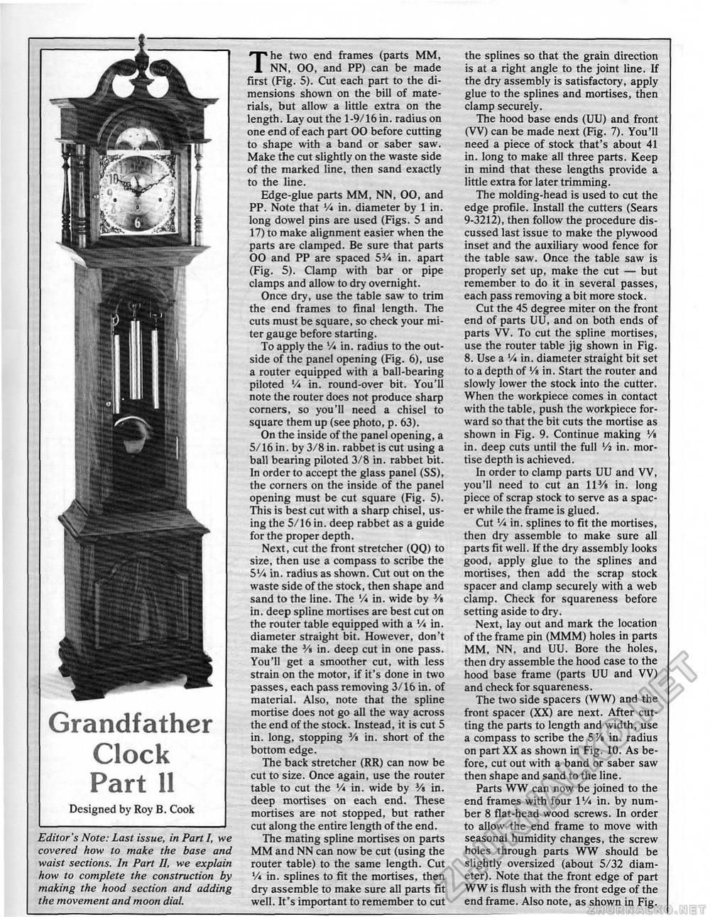
the splines so that the grain direction is at a right angle to the joint line. If the dry assembly is satisfactory, apply glue to the splines and mortises, then clamp securely. The hood base ends (UU) and front (W) can be made next (Fig- ?)• You'll need a piece of stock that's about 41 in. long to make all three parts. Keep in mind that these lengths provide a little extra for later trimming. The molding-head is used to cut the edge profile. Install the cutters (Sears 9-3212), then follow the procedure discussed last issue to make the plywood inset and the auxiliary wood fence for the table saw. Once the table saw is properly set up, make the cut — but remember to do it in several passes, each pass removing a bit more stock. Cut the 45 degree miter on the front end of parts UU, and on both ends of parts VV. To cut the spline mortises, use the router table jig shown in Fig. 8. Use a V* in. diameter straight bit set to a depth of Vtin. Start the router and slowly lower the stock into the cutter. When the workpiece comes in contact with the table, push the workpiece forward so that the bit cuts the mortise as shown in Fig. 9. Continue making Vt in. deep cuts until the full Vi in. mortise depth is achieved. In order to clamp parts UU and VV, you'll need to cut an 113/a in. long piece of scrap stock to serve as a spacer while the frame is glued. Cut V* in. splines to fit the mortises, then dry assemble to make sure all parts fit well. If the dry assembly looks good, apply glue to the splines and mortises, then add the scrap stock spacer and clamp securely with a web clamp. Check for squareness before setting aside to dry. Next, lay out and mark the location of the frame pin (MMM) holes in parts MM, NN, and UU. Bore the holes, then dry assemble the hood case to the hood base frame (parts UU and VV) and check for squareness. The two side spacers (WW) and the front spacer (XX) are next. After cutting the parts to length and width, use a compass to scribe the 57a in. radius on part XX as shown in Fig. 10. As before, cut out with a band or saber saw then shape and sand to the line. Parts WW can now be joined to the end frames with four 1V4 in. by number 8 flat-head wood screws. In order to allow the end frame to move with seasonal humidity changes, the screw holes through parts WW should be slightly oversized (about 5/32 diameter). Note that the front edge of part WW is flush with the front edge of the end frame. Also note, as shown in Fig. Grandfather Clock Part 11 Designed by Roy B. Cook Editor's Note: Last issue, in Part I, we covered how to make the base and waist sections. In Part U, we explain how to complete the construction by making the hood section and adding the movement and moon dial. The two end frames (parts MM, NN, 00, and PP) can be made first (Fig. 5). Cut each part to the dimensions shown on the bill of materials, but allow a little extra on the length. Lay out the 1-9/16 in. radius on one end of each part 00 before cutting to shape with a band or saber saw. Make the cut slightly on the waste side of the marked line, then sand exactly to the line. Edge-glue parts MM, NN, 00, and PP. Note that Vi in. diameter by 1 in. long dowel pins are used (Figs. 5 and 17) to make alignment easier when the parts are clamped. Be sure that parts 00 and PP are spaced 53A in. apart (Fig. 5). Clamp with bar or pipe clamps and allow to dry overnight. Once dry, use the table saw to trim the end frames to final length. The cuts must be square, so check your miter gauge before starting. To apply the V« in. radius to the outside of the panel opening (Fig. 6), use a router equipped with a ball-bearing piloted V* in. round-over bit. You'll note the router does not produce sharp corners, so you'll need a chisel to square them up (see photo, p. 63). On the inside of the panel opening, a 5/16 in. by 3/8 in. rabbet is cut using a ball bearing piloted 3/8 in. rabbet bit. In order to accept the glass panel (SS), the corners on the inside of the panel opening must be cut square (Fig. 5). This is best cut with a sharp chisel, using the 5/16 in. deep rabbet as a guide for the proper depth. Next, cut the front stretcher (QQ) to size, then use a compass to scribe the 5Vi in. radius as shown. Cut out on the waste side of the stock, then shape and sand to the line. The '/* in. wide by Vt in. deep spline mortises are best cut on the router table equipped with a V» in. diameter straight bit. However, don't make the ¥> in. deep cut in one pass. You'll get a smoother cut, with less strain on the motor, if it's done in two passes, each pass removing 3/16 in. of material. Also, note that the spline mortise does not go all the way across the end of the stock. Instead, it is cut 5 in. long, stopping Vt in. short of the bottom edge. The back stretcher (RR) can now be cut to size. Once again, use the router table to cut the V* in. wide by Vt in. deep mortises on each end. These mortises are not stopped, but rather cut along the entire length of the end. The mating spline mortises on parts MM and NN can now be cut (using the router table) to the same length. Cut % in. splines to fit the mortises, then dry assemble to make sure all parts fit well. It's important to remember to cut |


