Woodworker's Journal 1985-9-1, страница 42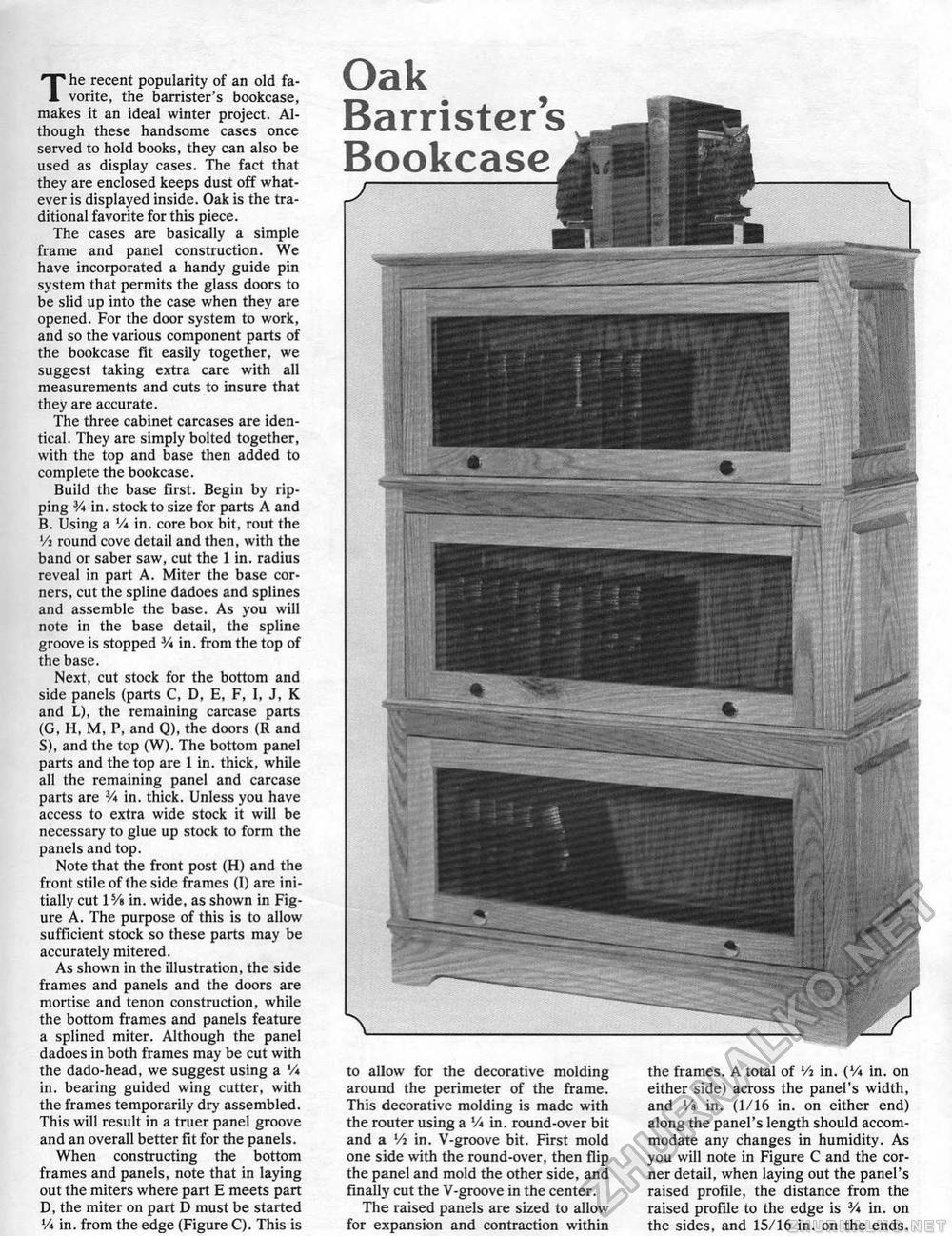
Oak Barrister's Bookcasei The recent popularity of an old favorite, the barrister's bookcase, makes it an ideal winter project. Although these handsome cases once served to hold books, they can also be used as display cases. The fact that they are enclosed keeps dust off whatever is displayed inside. Oak is the traditional favorite for this piece. The cases are basically a simple frame and panel construction. We have incorporated a handy guide pin system that permits the glass doors to be slid up into the case when they are opened. For the door system to work, and so the various component parts of the bookcase fit easily together, we suggest taking extra care with all measurements and cuts to insure that they are accurate. The three cabinet carcases are identical. They are simply bolted together, with the top and base then added to complete the bookcase. Build the base first. Begin by ripping V* in. stock to size for parts A and B. Using a '/* in. core box bit, rout the Vi round cove detail and then, with the band or saber saw, cut the 1 in. radius reveal in part A. Miter the base corners, cut the spline dadoes and splines and assemble the base. As you will note in the base detail, the spline groove is stopped V* in. from the top of the base. Next, cut stock for the bottom and side panels (parts C, D, E, F, I, J, K and L), the remaining carcase parts (G, H, M, P, and Q), the doors <R and S), and the top (W), The bottom panel parts and the top are 1 in. thick, while all the remaining panel and carcase parts are 3A in. thick. Unless you have access to extra wide stock it will be necessary to glue up stock to form the panels and top. Note that the front post (H) and the front stile of the side frames (I) are initially cut VA in. wide, as shown in Figure A. The purpose of this is to allow sufficient stock so these parts may be accurately mitered. As shown in the illustration, the side frames and panels and the doors are mortise and tenon construction, while the bottom frames and panels feature a splined miter. Although the panel dadoes in both frames may be cut with the dado-head, we suggest using a Vi in. bearing guided wing cutter, with the frames temporarily dry assembled. This will result in a truer panel groove and an overall better fit for the panels. When constructing the bottom frames and panels, note that in laying out the miters where part E meets part D, the miter on part D must be started Vi in. from the edge (Figure C). This is to allow for the decorative molding around the perimeter of the frame. This decorative molding is made with the router using a Vi in, round-over bit and a Vi in. V-groove bit. First mold one side with the round-over, then flip the panel and mold the other side, and finally cut the V-groove in the center. The raised panels are sized to allow for expansion and contraction within the frames. A total of Vi in. (Vi in. on either side) across the panel's width, and Vs in. (1/16 in. on either end) along the panel's length should accommodate any changes in humidity. As you will note in Figure C and the corner detail, when laying out the panel's raised profile, the distance from the raised profile to the edge is V* in. on the sides, and 15/16 in. on the ends. |


