Woodworker's Journal 1985-9-1, страница 43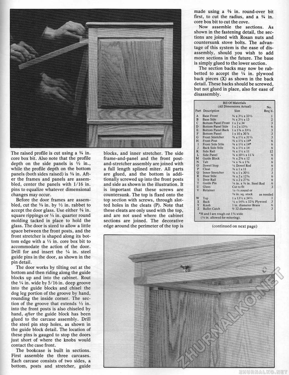
Bill Of Materials I,A!I Dimensions Actual) Bill Of Materials I,A!I Dimensions Actual)
*H and 1 are rough cut I s/« wide ('/«in. allowed for mitering). *H and 1 are rough cut I s/« wide ('/«in. allowed for mitering). made using a 3/a in. round-over bit first, to cut the radius, and a V* in. core box bit to cut the cove. Now assemble the sections. As shown in the fastening detail, the sections are joined with Rosan nuts and countersunk stove bolts. The advantage of this system is the ease of disassembly, should you wish to add more sections in the future. The base is simply glued to the lower section. The section backs may now be rab-betted to accept the Vi in. plywood back pieces (X) as shown in the back detail. These backs should be screwed, but not glued in place, also for ease of disassembly. The raised profile is cut using a V* in. core box bit. Also note that the profile depth on the side panels is Vi in., while the profile depth on the bottom panels (both sides raised) is 3/s in. After the frames and panels are assembled, center the panels with 1/16 in. pins to equalize whatever dimensional changes may occur. Before Lhe door frames are assembled, cut the 3/s in. by Vi in. rabbet to accept the door glass. Use either 3/« in. square rippings or V«in. quarter round molding tacked in place to hold the glass. The door is sized to allow a little space between the front posts, and the front stretcher is shaped along its bottom edge with a Vi in. core box bit to accommodate the action of the door. Drill for and insert the Vi in. steel guide pins in the door, as shown in the pin detail. The door works by tilting out at the bottom and then riding along the guide blocks up and into the cabinet. Rout the Vi in. wide by 5/16 in. deep groove into the guide blocks and chisel the dog leg portion of the groove by hand, rounding the inside corner. The section of the groove that extends Vi in. into the front posts is also chiseled by hand, after the guide block has been glued to the carcase assembly. Drill the steel pin stop holes, as shown in the guide block detail. The location of these pins is gauged to stop the doors just short of where the knobs would contact the case front. The bookcase is built in sections. First assemble the three carcases. Each carcase consists of two sides, a bottom, posts and stretcher, guide blocks, and inner stretcher. The side frame-and-pane! and the front post-and-stretcher assembly are joined with a full length splined miter. All parts are glued, and the bottom is additionally screwed up into the front posts and side as shown in the illustration. It is important that these screws are countersunk. The top is fixed onto the top section with screws, through slotted holes in the cleats (P). Note that these cleats are only used with the top, and are not used where the cabinet sections are joined. The decorative edge around the perimeter of the top is (continued on next page) |
||||||||||||||||||||||||||||||||||||||||||||||||||||||||||||||||||||||||||||||||||||||||||||||||||||||||||||||||


