Woodworker's Journal 1985-9-1, страница 48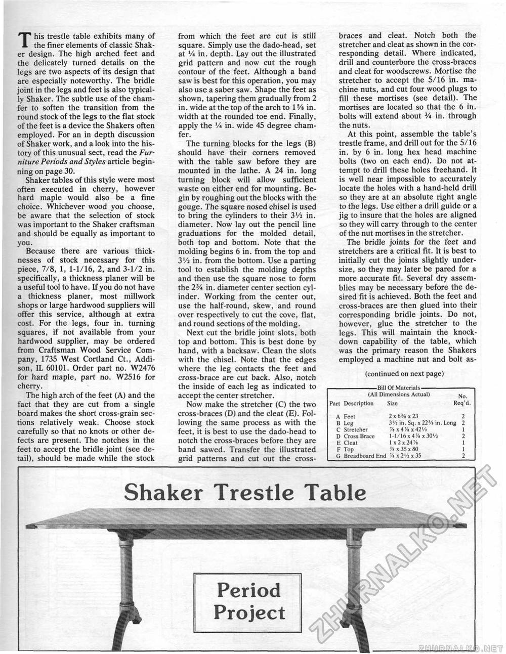
This trestle table exhibits many of the finer elements of classic Shaker design. The high arched feet and the delicately turned details on the legs are two aspects of its design that are especially noteworthy. The bridle joint in the legs and feet is also typically Shaker. The subtle use of the chamfer to soften the transition from the round stock of the legs to the flat stock of the feet is a device the Shakers often employed. For an in depth discussion of Shaker work, and a look into the history of this unusual sect, read the Furniture Periods and Styles article beginning on page 30. Shaker tables of this style were most often executed in cherry, however hard maple would aiso be a fine choice. Whichever wood you choose, be aware that the selection of stock was important to the Shaker craftsman and should be equally as important to you. Because there are various thicknesses of stock necessary for this piece, 7/8, 1, 1-1/16, 2, and 3-1/2 in. specifically, a thickness planer will be a useful tool to have, If you do not have a thickness planer, most millwork shops or large hardwood suppliers will offer this service, although at extra cost, For the legs, four in. turning squares, if not available from your hardwood supplier, may be ordered from Craftsman Wood Service Company, 1735 West Cortland Ct, Addison, IL 60101. Order part no. W2476 for hard maple, part no. W2516 for cherry. The high arch of the feet (A) and the fact that they are cut from a single board makes the short cross-grain sections relatively weak. Choose stock carefully so that no knots or other defects are present. The notches in the feet to accept the bridle joint (see detail), should be made while the stock from which the feet are cut is still square. Simply use the dado-head, set at V* in. depth. Lay out the illustrated grid pattern and now cut the rough contour of the feet. Although a band saw is best for this operation, you may also use a saber saw. Shape the feet as shown, tapering them gradually from 2 in. wide at the top of the arch to 15/a in. width at the rounded toe end. Finally, apply the V* in. wide 45 degree chamfer. The turning blocks for the legs (B) should have their corners removed with the table saw before they are mounted in the lathe. A 24 in. long turning block will allow sufficient waste on either end for mounting. Begin by roughing out the blocks with the gouge. The square nosed chisel is used to bring the cylinders to their 3Vj in. diameter. Now lay out the pencil line graduations for the molded detail, both top and bottom. Note that the molding begins 6 in. from the top and 3V4 in. from the bottom. Use a parting tool to establish the molding depths and then use the square nose to form the 2V* in. diameter center section cylinder, Working from the center out, use the half-round, skew, and round over respectively to cut the cove, flat, and round sections of the molding. Next cut the bridle joint slots, both top and bottom. This is best done by hand, with a backsaw. Clean the slots with the chisel. Note that the edges where the leg contacts the feel and cross-brace are cut back. Also, notch the inside of each leg as indicated to accept the center stretcher. Now make the stretcher (C) the two cross-braces (D) and the cleat (E). Following (he same process as with the feet, it is best to use the dado-head to notch the cross-braces before they are band sawed. Transfer the illustrated grid patterns and cut out the cross- braces and cleat. Notch both the stretcher and cleat as shown in the corresponding detail. Where indicated, drill and counterbore the cross-braces and cleat for woodscrews. Mortise the stretcher to accept the 5/16 in. machine nuts, and cut four wood plugs to fill these mortises (see detail). The mortises are located so that the 6 in. bolts will extend about V* in. through the nuts. At this point, assemble the table's trestle frame, and drill out for the 5/16 in. by 6 in. long hex head machine bolts (two on each end). Do not attempt to drill these holes freehand. It is well near impossible to accurately locate the holes with a hand-held drill so they are at an absolute right angle to the legs. Use either a drill guide or a jig to insure that the holes are aligned so they will carry through to the center of the nut mortises in the stretcher. The bridle joints for the feet and stretchers are a critical fit. It is best to initially cut the joints slightly under-size, so they may later be pared for a more accurate fit. Several dry assemblies may be necessary before the desired fit is achieved. Both the feet and cross-braces are then glued into their corresponding bridle joints. Do not, however, glue the stretcher to the legs. This will maintain the knockdown capability of the table, which was the primary reason the Shakers employed a machine nut and bolt as- (continued on next page) -Bill Of Materials—- (All Dimensions Actual) w0 Part Description Size Req'd, A Feet 2 x6V.* 23 2 B Leg J'/j in, Sq. x 22Vi in. Long 2 C Stretcher '/« x A '/> x 42 '/i I D Cross Brace 1 -1/16 x 4'/. x 30Vi 2 E Cleat 1x2x24'A 1 F Top 54 x 35 x 80 1 G Breadboard End '/ix2'/jx3S 2 Shaker Trestle Table |


