Woodworker's Journal 1985-9-3, страница 38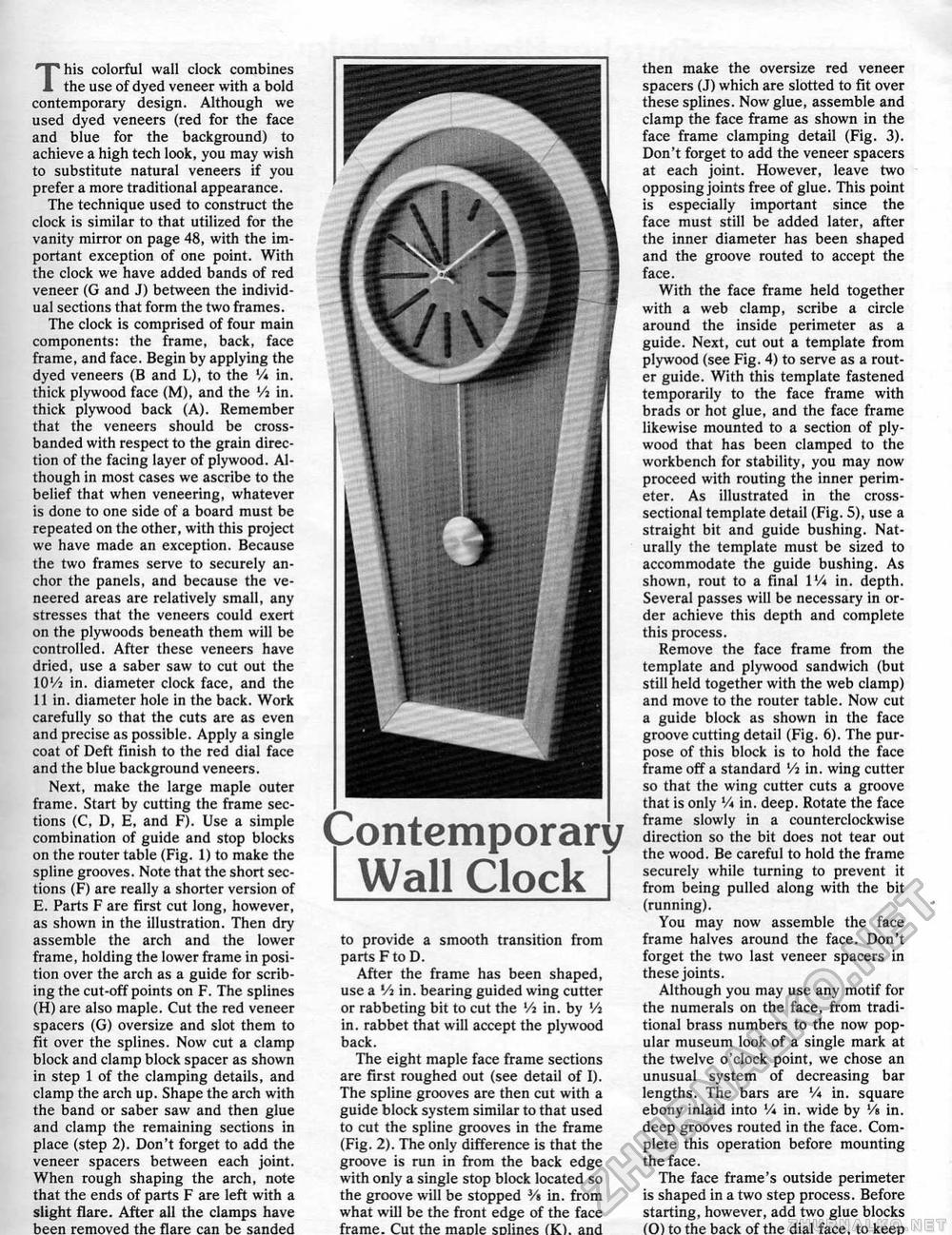
This colorful wall clock combines the use of dyed veneer with a bold contemporary design. Although we used dyed veneers (red for the face and blue for the background) to achieve a high tech look, you may wish to substitute natural veneers if you prefer a more traditional appearance. The technique used to construct the clock is similar to that utilized for the vanity mirror on page 48, with the important exception of one point. With the clock we have added bands of red veneer (G and J) between the individual sections that form the two frames. The clock is comprised of four main components: the frame, back, face frame, and face, Begin by applying the dyed veneers (B and L), to the V* in. thick plywood face (M), and the Vi in. thick plywood back (A). Remember that the veneers should be cross-banded with respect to the grain direction of the facing layer of plywood. Although in most cases we ascribe to the belief that when veneering, whatever is done to one side of a board must be repeated on the other, with this project we have made an exception. Because the two frames serve to securely anchor the panels, and because the veneered areas are relatively small, any stresses that the veneers could exert on the plywoods beneath them will be controlled. After these veneers have dried, use a saber saw to cut out the IOI/2 in. diameter clock face, and the 11 in. diameter hole in the back. Work carefully so that the cuts are as even and precise as possible, Apply a single coat of Deft Finish to the red dial face and the blue background veneers. Next, make the large maple outer frame. Start by cutting the frame sections (C, D, E, and F). Use a simple combination of guide and stop blocks on the router table (Fig. 1) to make the spline grooves. Note that the short sections (F) are really a shorter version of E. Parts F are first cut long, however, as shown in the illustration. Then dry assemble the arch and the lower frame, holding the lower frame in position over the arch as a guide for scribing the cut-off points on F. The splines (H) are also maple. Cut the red veneer spacers (G) oversize and slot them to fit over the splines. Now cut a clamp block and clamp block spacer as shown in step 1 of the clamping details, and clamp the arch up. Shape the arch with the band or saber saw and then glue and clamp the remaining sections in place (step 2). Don't forget to add the veneer spacers between each joint. When rough shaping the arch, note that the ends of parts F are left with a slight flare. After all the clamps have been removed the flare can be sanded Contemporary I Wall Clock I to provide a smooth transition from parts F to D. After the frame has been shaped, use a Vi in. bearing guided wing cutter or rabbeting bit to cut the Vi in. by Vi in. rabbet that will accept the plywood back. The eight maple face frame sections are first roughed out (see detail of I). The spline grooves are then cut with a guide block system similar to that used to cut the spline grooves in the frame (Fig. 2), The only difference is that the groove is run in from the back edge with only a single stop block located so the groove will be stopped ¥» in. from what will be the front edge of the face frame. Cut the maole solmes (K). and then make the oversize red veneer spacers (J) which are slotted to fit over these splines. Now glue, assemble and clamp the face frame as shown in the face frame clamping detail (Fig. 3). Don't forget to add the veneer spacers at each joint. However, leave two opposing joints free of glue. This point is especially important since the face must still be added later, after the inner diameter has been shaped and the groove routed to accept the face. With the face frame held together with a web clamp, scribe a circle around the inside perimeter as a guide. Next, cut out a template from plywood (see Fig. 4) to serve as a router guide. With this template fastened temporarily to the face frame with brads or hot glue, and the face frame likewise mounted to a section of plywood that has been clamped to the workbench for stability, you may now proceed with routing the inner perimeter. As illustrated in the cross-sectional template detail (Fig. 5), use a straight bit and guide bushing. Naturally the template must be sized to accommodate the guide bushing. As shown, rout to a final IV* in. depth. Several passes will be necessary in order achieve this depth and complete this process. Remove the face frame from the template and plywood sandwich (but still held together with the web clamp) and move to the router table. Now cut a guide block as shown in the face groove cutting detail (Fig. 6). The purpose of this block is to hold the face frame off a standard Vi in. wing cutter so that the wing cutter cuts a groove that is only V* in. deep. Rotate the face frame slowly in a counterclockwise direction so the bit does not tear out the wood. Be careful to hold the frame securely while turning to prevent it from being pulled along with the bit (running). You may now assemble the face frame halves around the face. Don't forget the two last veneer spacers in these joints. Although you may use any motif for the numerals on the face, from traditional brass numbers to the now popular museum look of a single mark at the twelve o'clock point, we chose an unusual system of decreasing bar lengths. The bars are V* in. square ebony inlaid into V* in. wide by Vs in. deep grooves routed in the face. Complete this operation before mounting the face. The face frame's outside perimeter is shaped in a two step process. Before starting, however, add two glue blocks (0) to the back of the dial face, to keep |


