Woodworker's Journal 1985-9-5, страница 46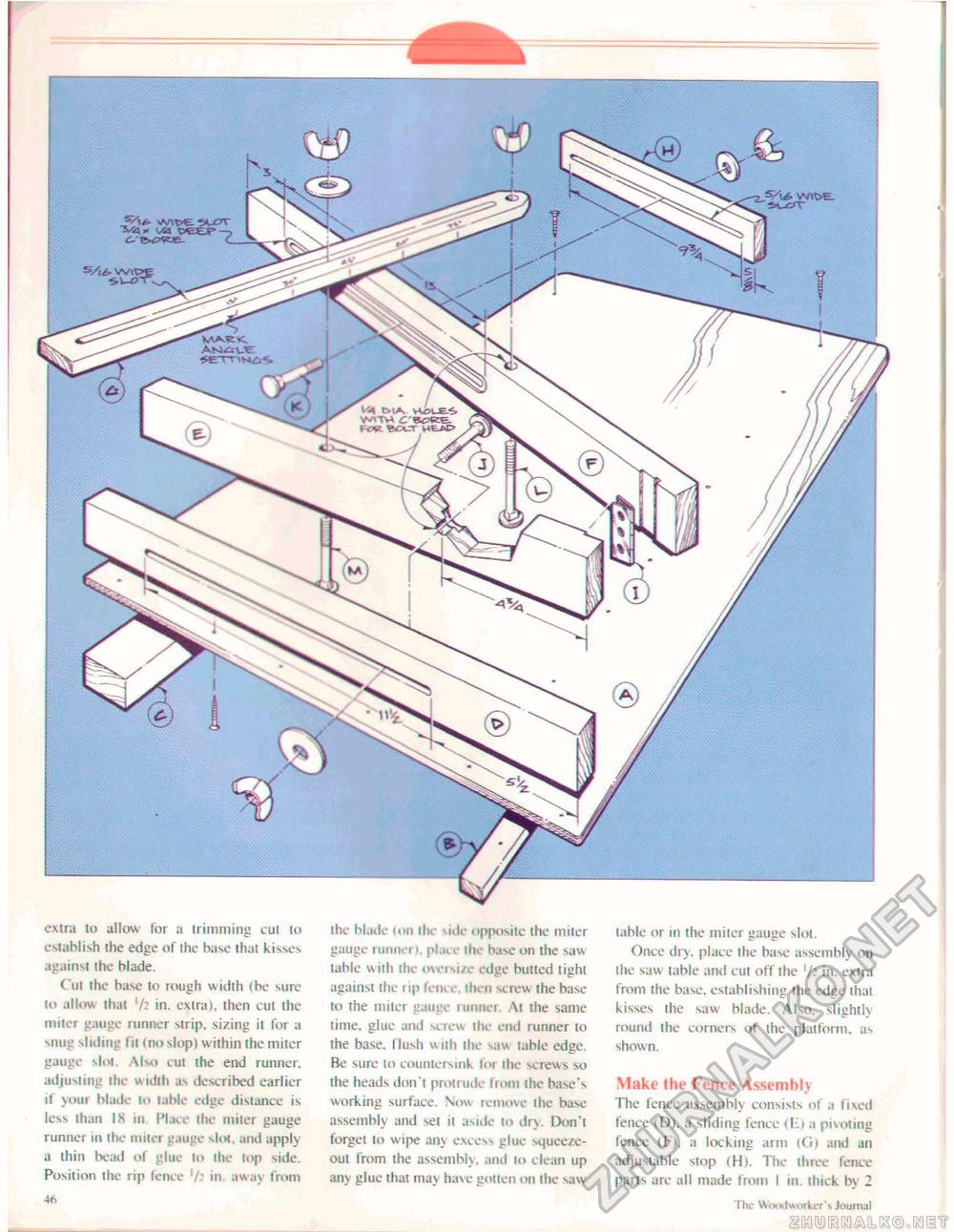
extra to allow for a trimming cut to establish the edge of the base that kisses against the blade. ("ui the base to rough width (be sure to allow that '/2 in. extra), then cut the miter gauge runner strip, sizing it for a snug sliding fit (no slop) within the miter gauge slot \lso cut the end runner, adjusting the width as described earlier if your blade to table edge distance is less than IS in. Place the miter gauge runner to the miter gauge slot, and apply a thin bead of glue to the top side. Position the rip fence '/: in away from 46 the blade ton the side opposite the miter gauge runner i. pin, e the base on the saw table wiih the oversize edge bulled light against the rip fence, then screw the base to the miter gauge runner. At ihe same time, glue and screw the end runner lo ihe base, flush with ihe saw table edge. Be sure to countersink for the screws so the heads don't protrude from the base's working surface. Now remove the base assembly and set il aside to dry. Don't forgei to wipe any excess glue squeeze-out from the assembly, and to clean up any glue that may have gotten on the saw table or in the miter gauge slot. Once dry, place the base assembly on the saw table and cut off the in. extra from the base, establishing the edge that kisses the saw blade. Also, slightly round the corners of the platform, as shown. Make the Fence Assembly The fence assembly consists of a Fixed fence (D), a sliding fence ilii a pivoting fence (F), a locking arm (Co and an adjustable stop (H). The three fence parts are all made from 1 m. thick by 2 46 The Woodworker's journal V'TH c l ov BDtT WEJ>£> |


