Woodworker's Journal 1985-9-5, страница 47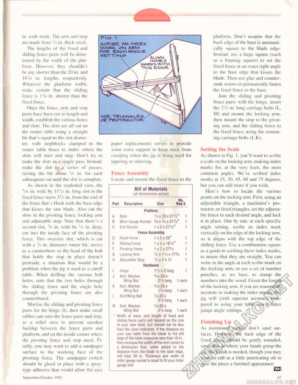
1 Avi MAC.VC on AKNA OS-E- TWAvWxLE-S in. wide stock. The arm and stop are made from '/- 111. thick stock. The lengths of the fixed and sliding fence parts w ill be determined by the width of the platform. However, they shouldn't be any shorter than the 20 in. and 187/s in. lengths, respectively. Whatever the platform width, make certain that the sliding fence is 1 '/k in. shorter than the fixed fence. Once ihe fence, arm and stop pans have been cut lo length and width, establish the various holes and slots. The slots are all cut on the router table using a straight hit that 's equal to the slot diameter. with stopblocks clamped to the rouier table fence to index where the slots will start and stop. Don't try to make the slots in a single pass. Instead, make the slot in ,a series of passes, raising the bii about in. for each subsequent cut until the slot is complete. As shown in the exploded view, the Via in. wide by 11'/- in. long slot in the fixed fence siarls 5'/- in. from ihe end of the fence that's flush with the base edge that kisses the saw blade. Also eul the slols in the pivoting fence, locking arm and adjustable slop. Note thai there'-, a second slot, in. wide by 'A in. deep, eul into ihe inside face of the pivoting fence. This oversize slot, which is cut with a V-t in. diameter router bit, serves as a counterbore so the head of the bolt thai holds the stop in place doesn't protrude, a situation that would be a problem when the jig is used as a cutoff table. When drilling the various bolt holes, note that the two holes through Ihe sliding fence and the single hole through ihe pivoting fence are also counterbored. Mortise the sliding and pivoting fence parts for the hinge (It. then make small rabbel cuts inlo the fence parls and slop, as a relief area to prevent sawdusi buildup between the fence parts and platform, and on the inside corner where the pivoting fence and slop meet. Finally, you may want to add a sandpaper surface to the working face of the pivoting fence. The sandpaper (which should be glued in place with a spray-lvpe adhesive that would allow for easy September/October 1992 paper replacement! serves to provide some extra support to keep stock from creeping when the jig is being used for tapering or miteiiug Fence Assembly Locate and mount the fixed lence to the Bill ol Materials (all dimensions actual) No. Part Description Size Req'd. No. Part Description Size Req'd.
' Wullti ol base, and length of tixed and sliding lence pans will depend on the size ol your saw (able, but should not be less than the sues indicated. It the distance on yout saw table from the blade to the left edge of the table measures less than 18 in then increase the width of the end runner to a dimension that, when added to the distance from the blade to the table edge, will total 20 in. Thickness and width ot mrter gauge runner is sued to fit your miter gauge slot platform. Don't assume lhat the back edge of ihe base is automatically square to the blade edge. Instead, use a large square (such as a framing square) to set ihe fixed fence at an exact right angle-to the base edge that kisses the blade. Then use glue and countersunk screw s lo permanently fasten the fixed fence to ihe base. Join the sliding and pivoting fence parts with the hinge, insert ihe 2xfr in. long carriage bolls (L. M) and mount the locking arm. then mount the stop to the pivoting arm, and the sliding fence to the fixed fence, using the remaining carriage bolts (J, K). Setting the Scale As shown in Fig. I, you'll want to scribe a scale on the locking arm, making index marks for. al the very teasl, the most common angles. We've scribed index marks at 15, 30, 45. 60 and 75 degrees, but you can add more if you wish. Here's how to locale the various points on ihe locking arm. First, using an adjustable triangle, a machinist's protractor. or fixed triangles, set the adjustable fence to each desired angle, and lock it in place. One by one. at each specific angle setting, scribe an index mark vertically on the edge of the locking arm. so it aligns with the top edge of the sliding fence. Use a combination square as a guide to scribing these index marks, lo insure that they are straight. You can write in the angle at each scribe mark on the locking arm, or use a set of number punches, as we have, to stamp the numbers inlo the wood. Given the length of the locking arm. if you arc reasonably accurate in making the index marks, this jig will yield superior accuracy compared to using your tabic saw's miter gauge angle settings. Finishing Up As mentioned earlier, don't sand surfaces. However, the back edge of the fixed fence should be gently rounded, since this is where your hands grasp (he jig. No finish is needed, though you may want to rub in a little penetrating oil to give ihe piece a finished appearance. E3i 47 |
||||||||||||||||||||||||||||||||||||||||||||||||||||||||||||


