Woodworker's Journal 1993-17-4, страница 51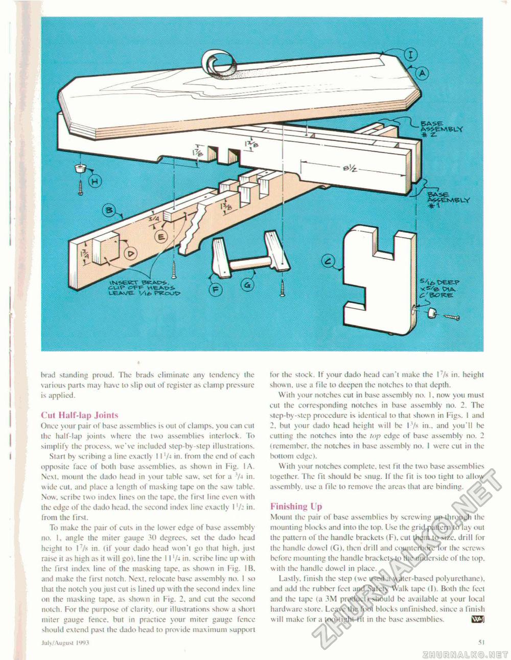
brad standing proud. The brads eliminate any tendency the various parts may have lo slip oul of register as clamp pressure is applied. Cut Half-lap Joints Once your pair of base assemblies is oul of clamps, you can cut the half-lap joints where the two assemblies interlock. To simplify the process, we've included step-by-step illustrations. I Start by scribing a line exactly 11 '/■> in. from the end of each opposite lace of both base assemblies, as shown in Fig. I A. Nexl. mount the dado head in your table saw, set for a 7 J in. w ide cut. and place a length of masking tape on the saw table. Now. scribe two index lines on the tape, the first line even w ith the edge of the dado head, the second index line exactly 1 7: in. from ihe first. To make the pair of cuts in the lower edge of base assembly no. I. angle the miter gauge 30 degrees, set the dado head height to t7/x in. (if your dado head won't go thai high, just raise it as high as it w ill go), line the 11 'A in. scribe line up w ith the first index line of ihe masking tape, as shown in Fig. IB. and make the first notch. Next, relocate base assembly no. 1 so that the notch you just cut is lined up with the second index line on the masking tape, as shown in Fig. 2, and cut the second notch. For the purpose of clarity, our illustrations show a short miter gauge fence, but in practice your miter gauge fence should extend past the dado head to provide maximum support Juh/Augusl IW3 tor the stock If your dado head can't make the I7/* in. height shown, use a file lo deepen the notches to thai depth. With your notches cut in base assembly no. I. now you must cut ihe corresponding notches in base assembly no, 2. The step-by-step procedure is identical to that shown in Figs. I and 2. but your dado head height will be 17s in., and you'll be cutting the notches into ihe lap edge of base assembly no. 2 (remember, the notches in base assembly no. I were cut in the bottom edge). With your notches complete, test fit the two base assemblies together. The fit should be snug. If the fit is too light lo allow assembly, use a file lo remove ihe areas lhat are binding. Finishing Up Mount ihe pair of base assemblies by screw ing up through the mounting Mocks and inio the top. Use the grid pattern lo lay oul Ihe pattern of the handle brackets (Fl. cut them to size, drill for ihe handle dowel <G), then drill and counterbore for the screws before mounting ihe handle brackets lo ihe underside of the top. with the handle dowel in place. Lastly, finish the step (we used a water-based poiyureihane), and add ihe rubber feel and Safety Walk tape (I). Both the feet and the tape (a 3M product) should be available at your local hardware store. Leave the foot blocks unfinished, since a finish w ill make for a loo-tighl fit in the base assemblies. |


