Woodworker's Journal 1993-17-5, страница 47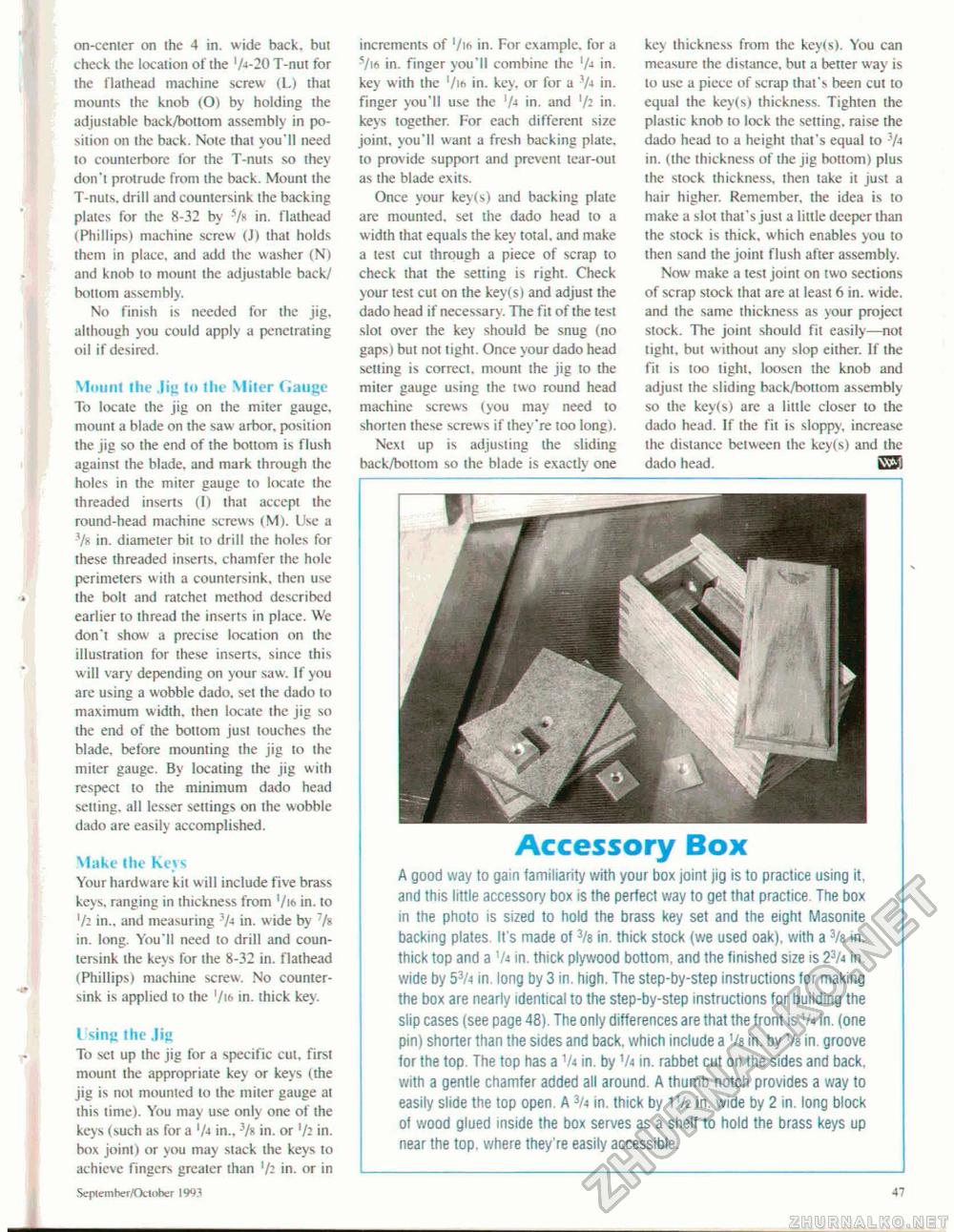
on-cemer on ihe 4 in. wide back, but check the location of the 1A-20 T-nut for the flathead machine screw (L) that mounts the knob (O) by holding the adjustable back/bottom assembly in position on the back. Note that you'll need to counterbore for the T-nuts so they don't protrude from the back. Mount the T-nuts, drill and countersink the backing plates for the 8-32 by 5 A in. flathead (Phillips) machine screw (J) that holds them in place, and add the washer (N) and knob to mount the adjustable back/ bottom assembly. No finish is needed for the jig, although you could apply a penetrating oil if desired. Mount the ,|if» to tiie Miter Gauge To locate the jig on the miter gauge, mount a blade on the saw arbor, position the jig so the end of the bottom is flush against the blade, and mark through the holes in the miter gauge to locate the threaded inserts (I) that accept the round-head machine screws (M). Use a Vs in. diameter bit to drill the holes for these threaded inserts, chamfer the hole perimeters with a countersink, then use the bolt and ratchet method described earlier to thread the inserts in place. We don't show a precise location on the illustration for these inserts, since this will vary depending on your saw. If you are using a wobble dado, set the dado to maximum width, then locate the jig so the end of the bottom just touches the blade, before mounting the jig to the miter gauge. By locating the jig with respect to the minimum dado head setting, all lesser settings on the wobble dado are easily accomplished. Make the Keys Your hardware kit will include five brass keys, ranging in thickness from '/16 in. to '/2 in., and measuring 3A in. wide by 7 A in. long. You'll need to drill and countersink the keys for the 8-32 in. flathead (Phillips) machine screw. No countersink is applied to the '/i6 in. thick key. I sing the Jig To set up the jig for a specific cut. first mount the appropriate key or keys (the jig is not mounted to the miter gauge at this time). You may use only one of the keys (such as for a 'A in., 3/s in. or '/; in. box joint) or you may stack the keys to achieve fingers greater than 'A in. or in increments of '/i* in. For example, for a SM in. finger you'll combine the 'A in. key with the 1/ie» in. key. or for a 'A in. finger you'll use the 'A in. and 'A in. keys together. For each different size joint, you'll want a fresh backing plate, to provide support and prevent tear-out as the blade exits. Once your key(s) and backing plate are mounted, set the dado head to a width that equals the key total, and make a test cut through a piece of scrap to check that the setting is right. Check your test cut on the key(s) and adjust the dado head if necessary. The fit of the test slot over the key should be snug (no gaps) but not tight. Once your dado head setting is correct, mount the jig to the miter gauge using the two round head machine screws (you may need to shorten these screws if they're too long). Next up is adjusting the sliding back/bottom so the blade is exactly one key thickness from the keyts). You can measure the distance, but a better way is lo use a piece of scrap that's been cut to equal the key(s) thickness. Tighten the plastic knob to lock the setting, raise the dado head to a height that's equal to 3A in. (the thickness of the jig bottom) plus the stock thickness, then take it just a hair higher. Remember, the idea is to make a slot that's just a little deeper than the slock is thick, which enables you to then sand the joint flush after assembly. Now make a test joint on two sections of scrap stock that are at least 6 in. wide, and the same thickness as your project stock. The joint should Fit easily—not tight, but without any slop either. If the fit is loo light, loosen ihe knob and adjust the sliding back/bottom assembly so the key(s) are a little closer to the dado head. If the fit is sloppy, increase the distance between the key(s) and ihe dado head. iSi Accessory Box A good way to gain familiarity with your box joint jig is to practice using it, and this little accessory box is the perfect way to get that practice The box in the photo is sized to hold the brass key set and the eight Masonite backing plates It's made of 3/e in. thick stock (we used oak), with a 3/s in. thick top and a 'A in. thick plywood bottom, and the finished size is 23A in. wide by 53A in. long by 3 in. high. The step-by-step instructions for making the box are nearly identical to the step-by-step instructions for building the slip cases (see page 48). The only differences are that the front is Va in. (one pin) shorter than the sides and back, which include a Va in. by 1/b in. groove for the top. The top has a 1A in. by 'A in. rabbet cut on the sides and back, with a gentle chamfer added all around. A thumb notch provides a way to easily slide the top open. A 3/4 in. thick by 1 Vz in. wide by 2 in. long block of wood glued inside the box serves as a shelf to hold the brass keys up near the top, where they're easily accessible. Seplemhcr/Otloher 1993 47 |


