Woodworker's Journal 2004-Winter, страница 17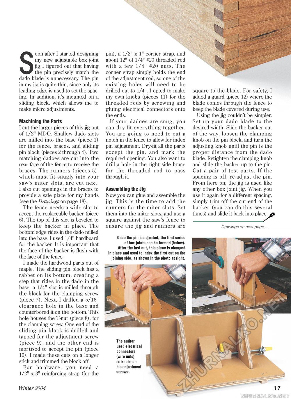
!;•:> v 1 ^srsp^rs — ' . . • Soon after I started designing my new adjustable box joint jig I figured out that having the pin precisely match the dado blade is unnecessary. The pin in my jig is quite thin, since only its leading edge is used to set the spacing. In addition, it's mounted on a sliding block, which allows me to make micro adjustments. Machining the Parts I cut the larger pieces of this jig out of 1/2" MDO. Shallow dado slots are milled into the base (piece 1) for the fence, braces, and sliding pin block (pieces 2 through 4). Two matching dadoes are cut into the rear face of the fence to receive the braces. The runners (pieces 5), which must fit snugly into your saw's miter slots, are cut next. I also cut openings in the braces to provide a safe place for my hands (see the Drawings on page 18). The fence needs a wide slot to accept the replaceable backer (piece 6). The top of this slot is beveled to keep the backer in place. The bottom edge rides in the dado milled into the base. I used 1/4" hardboard for the backer. It is important that the face of the backer is flush with the face of the fence. I made the hardwood parts out of maple. The sliding pin block has a rabbet on its bottom, creating a step that rides in the dado in the base; a 1/4" slot is milled through the block for the clamping screw (piece 7). Next, I drilled a 5/16" clearance hole in the base and counterbored it on the bottom. This hole houses the T-nut (piece 8), for the clamping screw. One end of the sliding pin block is drilled and tapped for the adjustment screw (piece 9), and the other end is mortised to accept the pin (piece 10). I made these cuts on a longer stick and trimmed the block off. For hardware, you need a 1/2" x 3" reinforcing strap (for the Winter 2004 17 pin), a 1/2" x 1" corner strap, and about 12" of 1/4" #20 threaded rod with a few 1/4" #20 nuts. The corner strap simply holds the end of the adjustment rod, so one of the existing holes will need to be drilled out to 1/4". I opted to make my own knobs (pieces 11) for the threaded rods by screwing and gluing electrical connectors onto the ends. If your dadoes are snug, you can dry-fit everything together. You are going to need to cut a notch in the fence to allow for index pin adjustment. Dry-fit all the parts except the pin, and mark the required opening. You also want to drill a hole in the right side brace for the threaded rod to pass through it. Assembling the Jig Now you can glue and assemble the jig. This is the time to add the runners for the miter slots. Set them into the miter slots, and use a square against the saw's fence to ensure the jig and runners are Once the pin is adjusted, the first series of box joints can be formed (below). After the last cut, this piece is clamped in place and used to index the first cut on the joining side, as shown in the photo at right. square to the blade. For safety, I added a guard (piece 12) where the blade comes through the fence to keep the blade covered during use. Using the jig couldn't be simpler. Set up your dado blade to the desired width. Slide the backer out of the way, loosen the clamping knob on the pin block, and turn the adjusting knob until the pin is the proper distance from the dado blade. Retighten the clamping knob and slide the backer up to the pin. Cut a pair of test parts. If the spacing is off, re-adjust the pin. From here on, the jig is used like any other box joint jig. When you use it again for a different spacing, simply trim off the cut end of the backer (you can do this several times) and slide it back into place. ^ _/ Drawings on next page.... The author used electrical connectors (wire nuts) as knobs on his adjustment screws. |


