Woodworker's Journal 2004-Winter, страница 49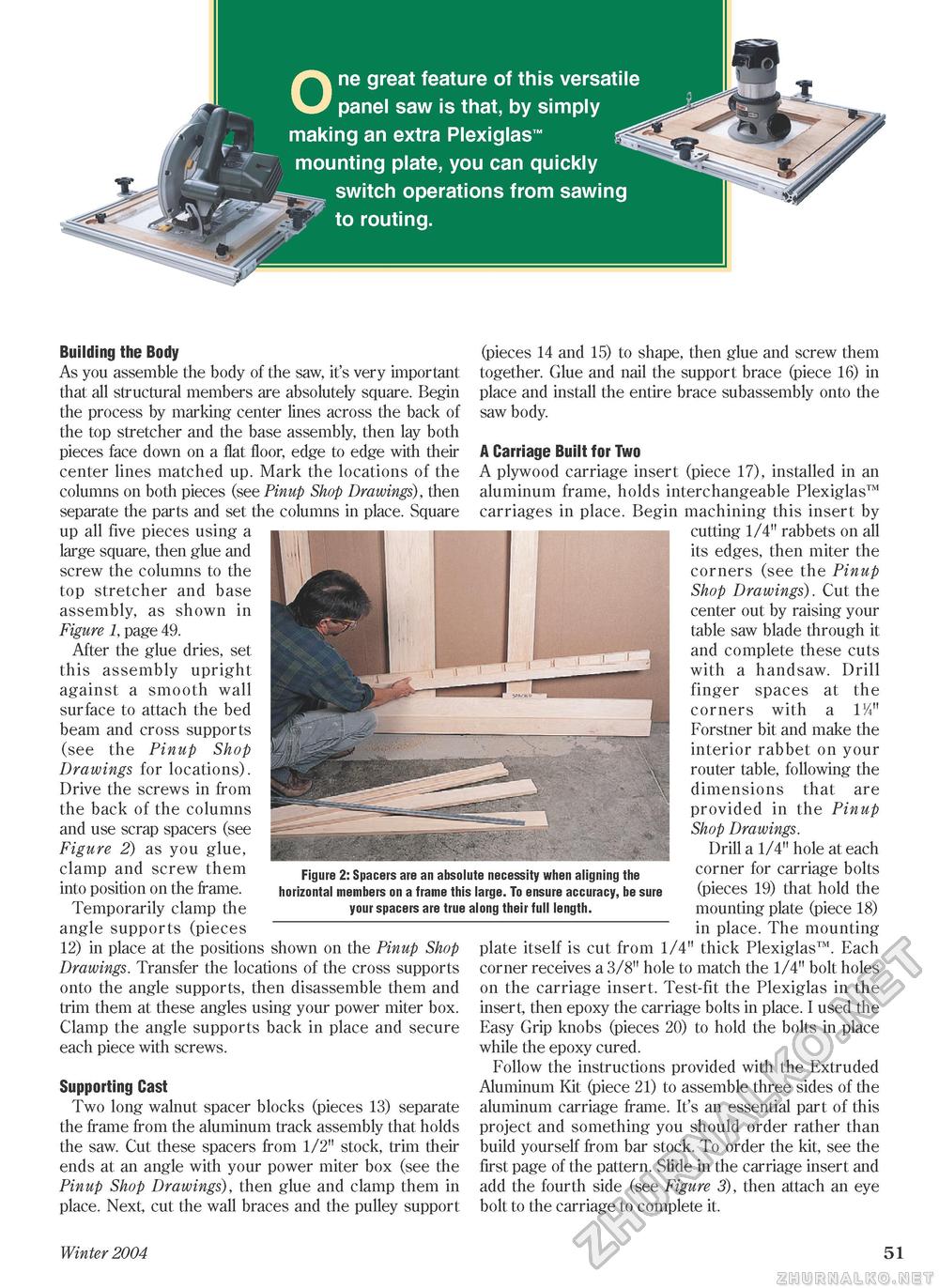
One great feature of this versatile panel saw is that, by simply making an extra Plexiglas™ mounting plate, you can quickly switch operations from sawing to routing. Building the Body As you assemble the body of the saw, it's very important that all structural members are absolutely square. Begin the process by marking center lines across the back of the top stretcher and the base assembly, then lay both pieces face down on a flat floor, edge to edge with their center lines matched up. Mark the locations of the columns on both pieces (see Pinup Shop Drawings), then separate the parts and set the columns in place. Square up all five pieces using a large square, then glue and screw the columns to the top stretcher and base assembly, as shown in Figure 1, page 49. After the glue dries, set this assembly upright against a smooth wall surface to attach the bed beam and cross supports (see the Pinup Shop Drawings for locations). Drive the screws in from the back of the columns and use scrap spacers (see Figure 2) as you glue, clamp and screw them into position on the frame. Temporarily clamp the angle supports (pieces 12) in place at the positions shown on the Pinup Shop Drawings. Transfer the locations of the cross supports onto the angle supports, then disassemble them and trim them at these angles using your power miter box. Clamp the angle supports back in place and secure each piece with screws. Supporting Cast Two long walnut spacer blocks (pieces 13) separate the frame from the aluminum track assembly that holds the saw. Cut these spacers from 1/2" stock, trim their ends at an angle with your power miter box (see the Pinup Shop Drawings), then glue and clamp them in place. Next, cut the wall braces and the pulley support Figure 2: Spacers are an absolute necessity when aligning the horizontal members on a frame this large. To ensure accuracy, be sure your spacers are true along their full length. (pieces 14 and 15) to shape, then glue and screw them together. Glue and nail the support brace (piece 16) in place and install the entire brace subassembly onto the saw body. A Carriage Built for Two A plywood carriage insert (piece 17), installed in an aluminum frame, holds interchangeable Plexiglas™ carriages in place. Begin machining this insert by cutting 1/4" rabbets on all its edges, then miter the corners (see the Pinup Shop Drawings). Cut the center out by raising your table saw blade through it and complete these cuts with a handsaw. Drill finger spaces at the corners with a P/i" Forstner bit and make the interior rabbet on your router table, following the dimensions that are provided in the Pinup Shop Drawings. Drill a 1/4" hole at each corner for carriage bolts (pieces 19) that hold the mounting plate (piece 18) in place. The mounting plate itself is cut from 1/4" thick Plexiglas™. Each corner receives a 3/8" hole to match the 1/4" bolt holes on the carriage insert. Test-fit the Plexiglas in the insert, then epoxy the carriage bolts in place. I used the Easy Grip knobs (pieces 20) to hold the bolts in place while the epoxy cured. Follow the instructions provided with the Extruded Aluminum Kit (piece 21) to assemble three sides of the aluminum carriage frame. It's an essential part of this project and something you should order rather than build yourself from bar stock. To order the kit, see the first page of the pattern. Slide in the carriage insert and add the fourth side (see Figure 3), then attach an eye bolt to the carriage to complete it. Winter 2004 51 |


