Woodworker's Journal fall-2009, страница 38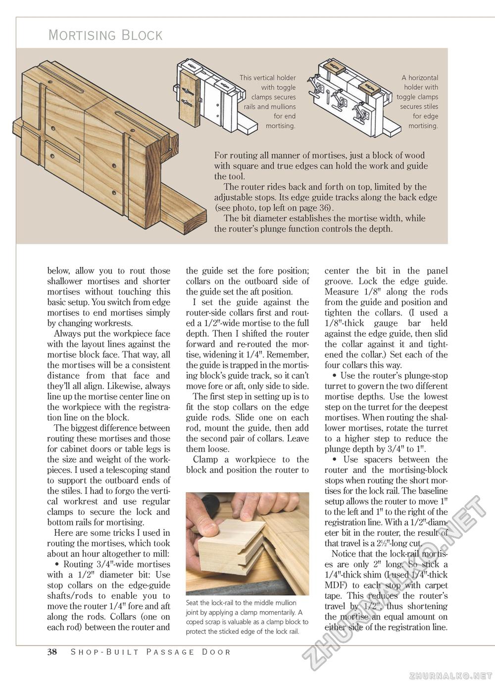
Mortising Block This vertical holder with toggle clamps secures rails and mullions for end mortising. A horizontal holder with toggle clamps secures stiles for edge mortising. For routing all manner of mortises, just a block of wood with square and true edges can hold the work and guide the tool. The router rides back and forth on top, limited by the adjustable stops. Its edge guide tracks along the back edge (see photo, top left on page 36). The bit diameter establishes the mortise width, while the router's plunge function controls the depth. below, allow you to rout those shallower mortises and shorter mortises without touching this basic setup. You switch from edge mortises to end mortises simply by changing workrests. Always put the workpiece face with the layout lines against the mortise block face. That way, all the mortises will be a consistent distance from that face and they'll all align. Likewise, always line up the mortise center line on the workpiece with the registration line on the block. The biggest difference between routing these mortises and those for cabinet doors or table legs is the size and weight of the work-pieces. I used a telescoping stand to support the outboard ends of the stiles. I had to forgo the vertical workrest and use regular clamps to secure the lock and bottom rails for mortising. Here are some tricks I used in routing the mortises, which took about an hour altogether to mill: • Routing 3/4"-wide mortises with a 1/2" diameter bit: Use stop collars on the edge-guide shafts/rods to enable you to move the router 1/4" fore and aft along the rods. Collars (one on each rod) between the router and the guide set the fore position; collars on the outboard side of the guide set the aft position. I set the guide against the router-side collars first and routed a 1/2"-wide mortise to the full depth. Then I shifted the router forward and re-routed the mortise, widening it 1/4". Remember, the guide is trapped in the mortising block's guide track, so it can't move fore or aft, only side to side. The first step in setting up is to fit the stop collars on the edge guide rods. Slide one on each rod, mount the guide, then add the second pair of collars. Leave them loose. Clamp a workpiece to the block and position the router to T J Seat the lock-rail to the middle mullion joint by applying a clamp momentarily. A coped scrap is valuable as a clamp block to protect the sticked edge of the lock rail. center the bit in the panel groove. Lock the edge guide. Measure 1/8" along the rods from the guide and position and tighten the collars. (I used a 1/8"-thick gauge bar held against the edge guide, then slid the collar against it and tightened the collar.) Set each of the four collars this way. • Use the router's plunge-stop turret to govern the two different mortise depths. Use the lowest step on the turret for the deepest mortises. When routing the shallower mortises, rotate the turret to a higher step to reduce the plunge depth by 3/4" to 1". • Use spacers between the router and the mortising-block stops when routing the short mortises for the lock rail. The baseline setup allows the router to move 1" to the left and 1" to the right of the registration line. With a 1/2"-diam-eter bit in the router, the result of that travel is a 2V2"-long cut. Notice that the lock-rail mortises are only 2" long. So stick a 1/4"-thick shim (I used 1/4"-thick MDF) to each stop with carpet tape. This reduces the router's travel by 1/2", thus shortening the mortise an equal amount on either side of the registration line. 38 Shop-Built Passage Door |


