Woodworker's Journal Summer-2008, страница 67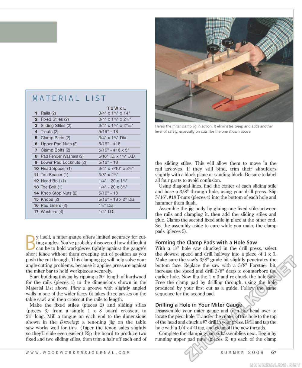
By itself, a miter gauge offers limited accuracy for cutting angles. You've probably discovered how difficult it can be to hold workpieces tightly against the gauge's short fence without them creeping out of position as you push the cut through. This clamping jig will help solve your angle-cutting problems, because it applies pressure against the miter bar to hold workpieces securely. Start building this jig by ripping a 30" length of hardwood for the rails (pieces 1) to the dimensions shown in the Material List above. Plow a groove with slightly angled walls in one of the wider faces (it takes three passes on the table saw) and then crosscut the rails to length. Make the fixed stiles (pieces 2) and sliding stiles (pieces 3) from a single 1x8 board crosscut to 23/' long. Mill a tongue on each end to the dimensions shown in the Drawing: a tenoning jig on the table saw works well for this. (Taper the tenon sides slightly so they'll slide even easier.) Rip the board to produce two fixed and two sliding stiles, then trim a hair off each end of Here's the miter clamp jig in action. It eliminates creep and adds another level of safety, especially on cuts like the one shown above. the sliding stiles. This will allow them to move in the rail grooves. If they still bind, trim their shoulders slightly with a block plane or sanding block. Be sure to label all four parts to avoid confusion. Using diagonal lines, find the center of each sliding stile and bore a 3/8" through hole, using your drill press. Slip 5/16", #18 T-nuts (pieces 4) into the bottom of each hole and hammer them flush. Assemble the jig body by gluing one fixed stile between the rails and clamping it, then add the sliding stiles and glue. Clamp the second fixed stile in place at the other end. Set the assembly aside to cure while you make the clamp pads (pieces 5). Forming the Clamp Pads with a Hole Saw With a 13/4" hole saw chucked in the drill press, select the slowest speed and drill halfway into a piece of 1 x 3. Make sure the saw's 3/8" guide bit slightly penetrates the bottom face. Replace the saw with a 5/8" Forstner bit, increase the speed and drill 3/8" deep to counterbore the earlier hole. Now flip the 1 x 3 and re-chuck the hole saw. Free the clamp pad by drilling through, using the hole produced by your first cut as a guide. Follow the same sequence for the second pad. Drilling a Hole in Your Miter Gauge Disassemble your miter gauge and turn the head over to locate the pivot hole. Transfer the center of this hole to the top of the head and chuck a #7 drill in your press. Drill and tap the hole with a 1/4 x #20 tap, and clean off the new threads. Complete the clamping pad subassemblies next. Begin by running upper pad nuts (pieces 6) up each of the clamp www.woodworkersjourna l . c o m summer 2008 67 |


