Creative Woodworks & crafts 1999-11, страница 45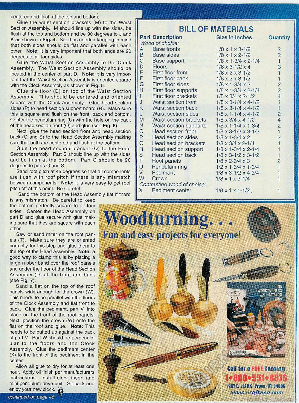
Woodturning... Fun and easy projects for everyone! Cam for a-FREE Catalog mi E. 1120 S. Provo, UT 84606 iviOw.crqftusa.com centered and flush at the top and bottom. Glue the waist section brackets (M) to the Waist Section Assembly. M should line up with the sides, be flush at the top and bottom and be 90 degrees to J and K as shown in Fig, 4. Sand as needed keeping in mind that both sides should be flat and parallel with each other. Note: it is very important that both ends are 90 degrees to all four sides. Glue the Waist Section Assembly to the Clock Assembly. The Waist Section Assembly should be located in the center of part D. Note: it is very important that the Waist Section Assembly is oriented square with the Clock Assembly as shown in Fig. 5. Glue the floor (D) on top of the Waist Section Assembly. This should be centered and oriented square with the Clock Assembly. Glue head section sides (P) to head section support board (R). Make sure this is square and flush on the front, back and bottom. Center the pendulum ring (U) with the hole on the back of the head section front (O) and glue (see Fig. 6). Next, glue the head section front and head section back (O and S) to the Head Section Assembly making sure that both are centered and flush at the bottom. Glue the head section bracket <Q) to the Head Section Assembly. Part S should line up with the sides and be flush at the bottom. Part Q should be 90 degrees to parts O and S. Sand roof pitch at 45 degrees so that all components are flush with roof pitch if there is any mismatch between components. Note: it is very easy to get roof pitch off at this point. Be Careful. Sand the bottom of the Head Assembly flat if there is any mismatch. Be careful to keep the bottom perfectly square to all four sides. Center the Head Assembly on part D and glue secure with glue making sure that they are square with each other. Saw or sand miter on the roof panels (T). Make sure they are oriented correctly for this step and glue them to the top of the Head Assembly. Note: a good way to clamp this is by placing a large rubber band over the roof panels and under the floor of the Head Section Assembly (D) at the front and back (see Fig. 7). Sand a flat on the top of the roof panels wide enough for the crown (W). This needs to be parallel with the floors of the Clock Assembly and flat front to back. Glue the pediment, part V, into place on the front of the roof panels. Next, position the crown (W) onto the flat on the roof and glue. Note: This needs to be butted up against the back of part V. Part W should be perpendicular to the floors and the Clock Assembly. Glue the pediment center (X) to the front of the pediment in the center. Allow all glue to dry for at least one hour. Apply oil finish per manufacturers instructions. Install clock insert and mini pendulum drive unit. Sit back and enjoy your new clock. jf| continued on page 46 Part Description Wood of choice: A Base fronts B Base sides C Base support D Floors E First floor front F First floor back G First floor sides H First floor supports I First floor brackets J Waist section front K Waist section back L Waist section sides M Waist section brackets N Waist section supports O Head section front P Head section sides Q Head section brackets R Head section support S Head section back T Roof panels U Pendulum ring V Pediment W Crown Contrasting wood of choice: X Pediment center BILL OF MATERIALS Size In Inches 1/8x1 x 3-1/2 1/8 x 1 x 2-1/2 1/8x1-3/4x2-1/4 1/8x3-1/2x4 1/8x2x3-1/2 1/8 x 2 x 3-1/2 1/8x1-3/4x2 1/8x1-3/4x2-1/4 1/8x3/4x2-1/2 1/8x3-1/4x4-1/2 1/8x3-1/4x4-1/2 1/8x1-1/4x4-1/2 1/8 x 3/4 x 4-1/2 1/8x1-1/4x1-3/4 1/8x3-1/2x3-1/2 1/8x1-3/4x2 1/8x3/4x2-1/4 1/8x1-3/4x2-1/4 1/8x3-1/2x3-1/2 1/8x2-3/4x3 1/2x1-3/4x1-3/4 1/8 x 3-1/2 x 4-3/4 1/8 x 1 x 3-1/4 1/8x1 x 1-1/2. Quantity 2 2 1 3 1 1 2 2 4 1 1 2 4 2 1 2 4 1 1 2 1 1 1 |


