10 - Heavy Duty Lathe Stand, страница 20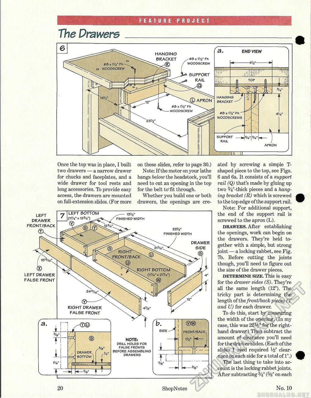
FEATURE PROJECT The Drawers Once the top was in place, I built two drawers — a narrow drawer for chucks and faceplates, and a wide drawer for tool rests and long accessories. To provide easy access, the drawers are mounted on full-extension slides. (For more on these slides, refer to page 30.) Note: If the motor on your lathe hangs below the headstock, you'll need to cut an opening in the top for the belt to'fit through. Whether you build one or both drawers, the openings are cre ated by screwing a simple T-shaped piece to the top, see Figs. 6 and 6a. It consists of a support rail (Q) that's made by gluing up two 3/4"-thick pieces and a hanging bracket (R) which is screwed to the top edge of the support rail. Note: For additional support, the end of the support rail is screwed to the apron (L). drawers. After establishing the openings, work can begin on the drawers. They're held together with a simple, but strong joint — a locking rabbet, see Fig. 7b. Before cutting the joints though, you'll need to figure out the size of the drawer pieces. determine size. This is easy for the draiver sides (S). They're all the same length (12"). The tricky part is determining the length of the front/back pieces (T and U) for each drawer. To do this, start by measuring the width of the opening. (In my case, this was 231/£" for the right-hand drawer.) Then subtract the amount of clearance you'll need for the drawer slides. (Each of the slides I used required V2" clearance on each side for a total of 1".) The last thing to take into account is the locking rabbet joints. After subtracting (3/s" on each LEFT DRAWER FRONT/BACK DRAWER SIDE 22V2" FINISHED WIDTH LEFT DRAWER FALSE FRONT RIGHT DRAWER FALSE FRONT NOTE: DRILL HOLES FOR FALSE FRONTS BEFORE ASSEMBLING DRAWERS DRAWER l/4" BOTTOM ) ( LEFT BOTTOM (HV4" x 123/4") 131/2" FINISHED WIDTH 20 ShopNotes No. 10 |


