15 - Sliding Table, страница 6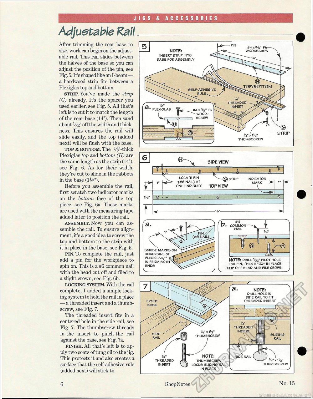
JIGS & ACCESSORIES Adjustable RailAfter trimming the rear base to size, work can begin on the adjustable rail. This rail slides between the halves of the base so you can adjust the position of the pin, see Fig. 5. It's shaped like an I-beam— a hardwood strip fits between a Plexiglas top and bottom. strip. You've made the strip (G) already. It's the spacer you used earlier, see Fig. 5. All that's left is to cut it to match the length of the rear base (14"). Then sand about V32" off the width and thickness. This ensures the rail will slide easily, and the top (added next) will be flush with the base. top & bottom. The V8"-thick Plexiglas top and bottom (H) are the same length as the strip (14"), see Fig. 6. As for their width, they're cut to slide in the rabbets in the base (IV2"). Before you assemble the rail, first scratch two indicator marks on the bottom face of the top piece, see Fig. 6a. These marks are used with the measuring tape added later to position the rail. assembly. Now you can assemble the rail. To ensure alignment, it's a good idea to screw the top and bottom to the strip with it in place in the base, see Fig. 5. pin. To complete the rail, just add a pin for the workpiece to spin on. This is a #6 common nail with the head cut off and filed to a slight crown, see Fig. 6b. locking system. With the rail complete, I added a simple locking system to hold the rail in place — a threaded insert and a thumbscrew, see Fig. 7. The threaded insert fits in a centered hole in the side rail, see Fig. 7. The thumbscrew threads in the insert to pinch the rail against the base, see Fig. 7a. finish. All that's left is to apply two coats of tung oil to the jig. This protects it and also creates a surface that the self-adhesive rale (added next) will stick to.
NOTE: PRILL 3/32" PILOT HOLE FOR PIN, THEN EPOXY IN PLACE CLIP OFF HEAD AND FILE CROWN UNDERSIDE OF PLEXIGLAS,1" IN FROM BOTH ENDS V_ RAIL THREADED INSERT !4" x 11/2" THUMBSCREW NOTE: THUMBSCREW LOCKS SLIDING RAIL IN PLACE FRONT BASE NOTE: DRILL HOLE IN SIDE RAIL TO FIT THREADED INSERT THREADED INSERT T SIDE RAIL V_ SLIDING RAIL 1V2" THUMBSCREW 6 ShopNotes No. 15 |
|||||||||||||||||||||||||||||||||||||||||


